High-power charging device used for electric bus

A high-power charging and electric bus technology, applied in the direction of electric vehicle charging technology, electric vehicles, charging stations, etc., can solve the problems of few outlets, few outlets of automobile gas stations, limited space of automobile gas stations, etc., to prolong the service life, Small weight and simple structure

Inactive Publication Date: 2018-05-15
SUZHOU IND PARK HESHUN ELECTRIC CO LTD
View PDF6 Cites 0 Cited by
  • Summary
  • Abstract
  • Description
  • Claims
  • Application Information

AI Technical Summary

Benefits of technology

This patented technology describes different ways to improve power charger devices used in electrically driven cars (EVC). These improvements include improved design features such as supporting chains or carrying cables along rails, reducing their size while still providing sufficient space inside them, improving safety during use due to reduced exposure to external elements like rainwater, snow, ice, etc., increasing energy storage capacity without adding extra weights, making it lighter than traditional batteries, enabling longer battery lifetimes, simplifying maintenance tasks, allowing for more flexibility in terms of how long they may operate before requiring replacement, and having multiple functions integrated into each other.

Problems solved by technology

This patented technical solution described for reducing environmental concerns associated with fossil fuels-based transportation includes both Hybrid Electric Vehicles (HEVs), and Pure Electrical Powered Transportations System(PESS). However, current methods require significant investment on infrastructure such as gas station facilities while achieving similar benefits compared to traditional power sources like Gasoline/ Diesel.

Method used


Image

  • High-power charging device used for electric bus
  • High-power charging device used for electric bus
  • High-power charging device used for electric bus

Examples


Embodiment 1

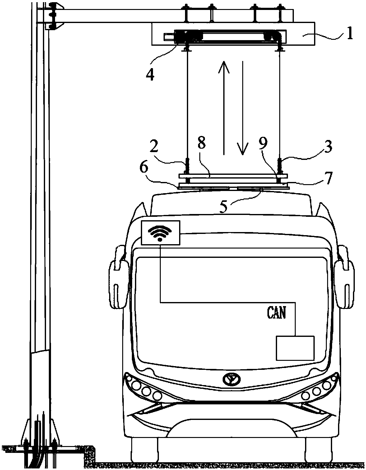
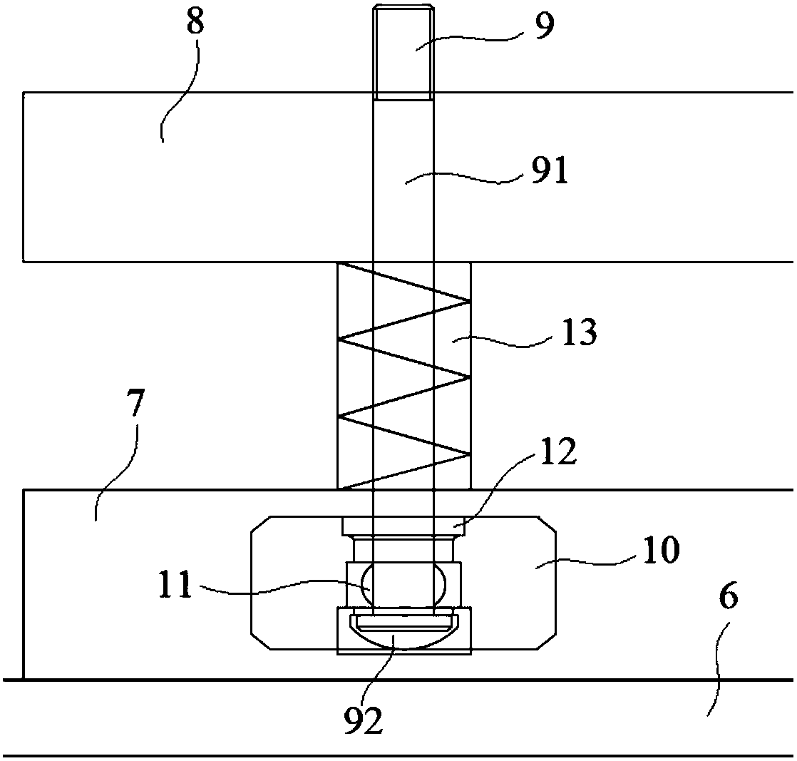
[0029] Embodiment 1: A high-power charging device for electric buses, including a chain warehouse 1, a left support chain 2 and a right support chain 3 arranged in the chain warehouse 1, a support chain drive mechanism 4 and a The charging pole 6 contacted by the electrode 5, the supporting chain driving mechanism 4 is located in the chain warehouse 1 and connected with the upper ends of the left supporting chain 2 and the right supporting chain 3 respectively, and is used to drive the left supporting chain 2 and the right supporting chain 3 to move up and down , the lower ends of the left support chain 2 and the right support chain 3 are installed and connected to the charging pole 6, and the charging pole 6 is connected to the left support chain 2 and the right support chain 3 through a mounting plate 7;

[0030] The lower ends of the left support chain 2 and the right support chain 3 are respectively fixedly connected with a fixed plate 8, the fixed plate 8 is located directly

Embodiment 2

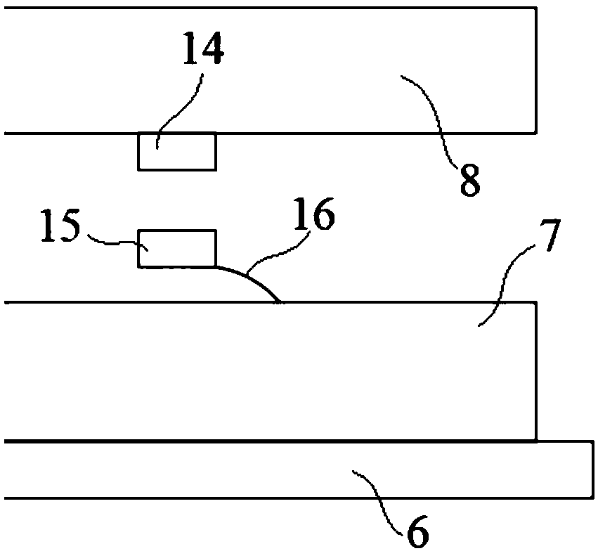
[0034] Embodiment 2: A high-power charging device for electric buses, including a chain warehouse 1, a left support chain 2 and a right support chain 3 arranged in the chain warehouse 1, a support chain drive mechanism 4 and a The charging pole 6 contacted by the electrode 5, the supporting chain driving mechanism 4 is located in the chain warehouse 1 and connected with the upper ends of the left supporting chain 2 and the right supporting chain 3 respectively, and is used to drive the left supporting chain 2 and the right supporting chain 3 to move up and down , the lower ends of the left support chain 2 and the right support chain 3 are installed and connected to the charging pole 6, and the charging pole 6 is connected to the left support chain 2 and the right support chain 3 through a mounting plate 7;

[0035] The lower ends of the left support chain 2 and the right support chain 3 are respectively fixedly connected with a fixed plate 8, the fixed plate 8 is located directly


PUM


Abstract

The invention discloses a high-power charging device used for an electric bus. The device includes a chain bin, a left supporting chain, a right supporting chain, a supporting chain driving mechanismand a charging electrode for being in contact with a bus roof power receiving electrode, wherein the left supporting chain and the right supporting chain are arranged in the chain bin; the supportingchain driving mechanism is positioned in the chain bin, connected with the upper ends of the left supporting chain and the right supporting chain and used for driving the left supporting chain and theright supporting chain to move up and down; two magnetic sensors are arranged on the lower surface of a fixing plate, magnets corresponding to the magnetic sensors are arranged on the upper surface of a mounting plate, a first transmission gear and a second transmission gear are installed at both ends of the outer side surface of a first hanging plate or a second ganging plate respectively, and adriving gear and a driven gear are installed on the outer side surface, corresponding to the first transmission gear, of the first hanging plate or the second hanging plate. According to the device,the space can be effectively saved, and the device is small in size, low in weight, simple in structure and capable of achieving a protection function on a chain and a charging electrode.

Description


Claims


Application Information

Patent Timeline
Owner SUZHOU IND PARK HESHUN ELECTRIC CO LTD
Why Eureka
Try Eureka