Spiral feeding device

A screw feeding and screw technology is applied in the field of glass substrate manufacturing, which can solve the problems of unsmooth feeding of raw materials, block-shaped feeding, and destruction of the rigor of the raw materials, so as to improve the weighing accuracy and reduce the agglomeration of raw materials.

Inactive Publication Date: 2018-05-29
WUHU TUNGHSU PHOTOELECTRIC SCI & TECHCO +2
View PDF8 Cites 0 Cited by
  • Summary
  • Abstract
  • Description
  • Claims
  • Application Information

AI Technical Summary

Benefits of technology

The technical effect of this patented technology is that it introduces an improved method for mixing powders with liquids without causing them clump together or getting stuck during storage time due to their tendency towards sticking when stored at high temperatures (approaching 30°C). This results in more accurate weight measurement compared to existing methods such as vibrated tables used earlier times.

Problems solved by technology

This technical problem addressed by this patented technology relates to improving the flowability and conveyance efficiency for liquids crystals used in manufacturing processes such as making them more stable without being affected from any issues like clumpedness caused by aggregating ingredients within the feeder's bin.

Method used


Image

  • Spiral feeding device
  • Spiral feeding device
  • Spiral feeding device

Examples


Embodiment Construction

[0031] Specific embodiments of the present disclosure will be described in detail below in conjunction with the accompanying drawings. It should be understood that the specific embodiments described here are only used to illustrate and explain the present disclosure, and are not intended to limit the present disclosure.

[0032] In this disclosure, unless stated otherwise, the used orientation words such as "up, down, left, right" generally refer to the upper, lower, left, and right in the drawings, and "inner, outer" refers to Inside and outside relative to the outline of the part.

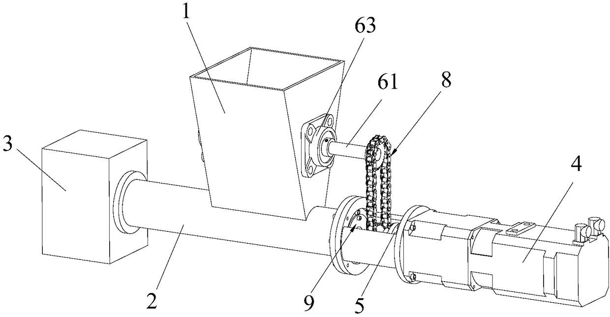
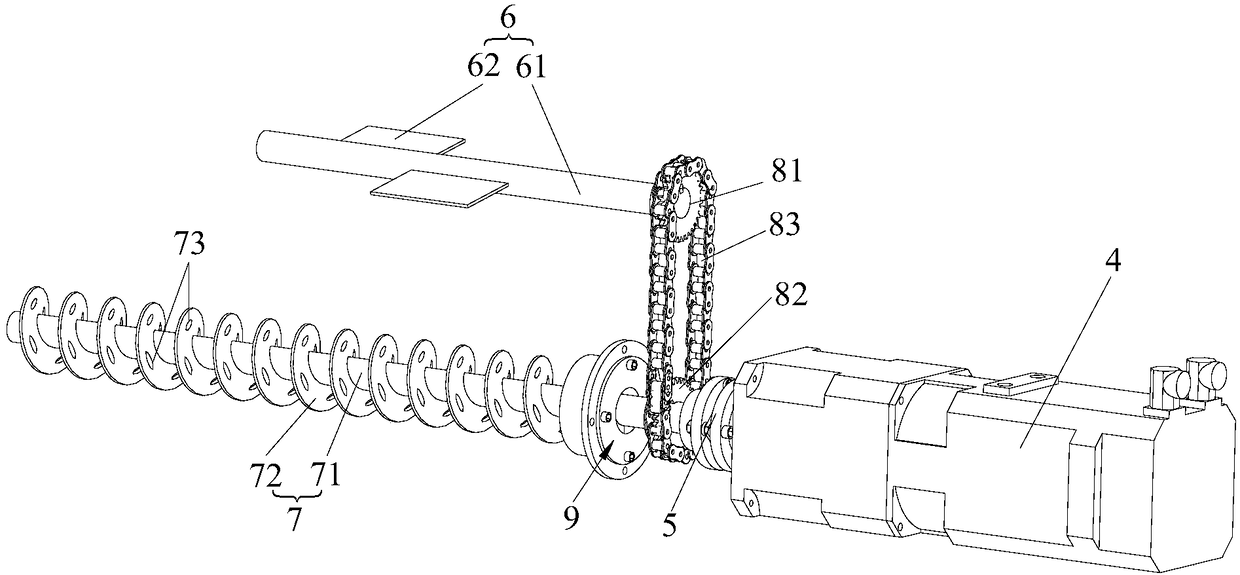
[0033] see figure 1 and figure 2 , The present disclosure relates to a screw feeding device, the screw feeding device includes a feed hopper 1 , a screw channel 2 and a feeder 3 connected in sequence. Specifically, the outlet of the feed hopper 1 is positioned on the sidewall of the screw channel 2, and the feeder 3 is positioned at the axial end of the screw channel 2, so that the screw mechani


PUM


Abstract

The invention relates to a spiral feeding device. The spiral feeding device comprises a feeding hopper (1), a spiral material passage (2) and an unloader (3) which communicate with one another sequentially. A spiral mechanical mounted in the spiral material passage (2) can convey raw materials from the feeding hopper (1) into the unloader (3), the spiral feeding device further comprises a stirringmechanism (6) used for conducting primary stirring on the raw materials, and the stirring mechanism (6) is mounted in the feeding hopper (1). By mounting the stirring mechanism in the feeding hopper,primary stirring can be conducted on the raw materials, caking of the raw materials is reduced accordingly, and the weighing precision of dosing is improved effectively.

Description


Claims


Application Information

Patent Timeline
Owner WUHU TUNGHSU PHOTOELECTRIC SCI & TECHCO
Why Eureka
Try Eureka