License plate recognition camera with rotation function

A technology of license plate recognition and rotation function, which is applied in the field of camera, which can solve the problems of limited field of view of the camera and the inability to adjust the horizontal angle, etc., so as to improve the service life, save power supply, and improve the field of view.

Pending Publication Date: 2018-05-29
嘉兴贝斯特电子技术有限公司
View PDF1 Cites 7 Cited by
  • Summary
  • Abstract
  • Description
  • Claims
  • Application Information

AI Technical Summary

Problems solved by technology

[0003] However, the current cameras are basically fixed, and some can only be adjusted up and down, and the horizontal angle cannot be adjusted. Th

Method used


Image

  • License plate recognition camera with rotation function
  • License plate recognition camera with rotation function

Examples


Embodiment Construction

[0017] In order to make the technical means, creative features, goals and effects achieved by the present invention easy to understand, the present invention will be further described below in conjunction with specific embodiments.

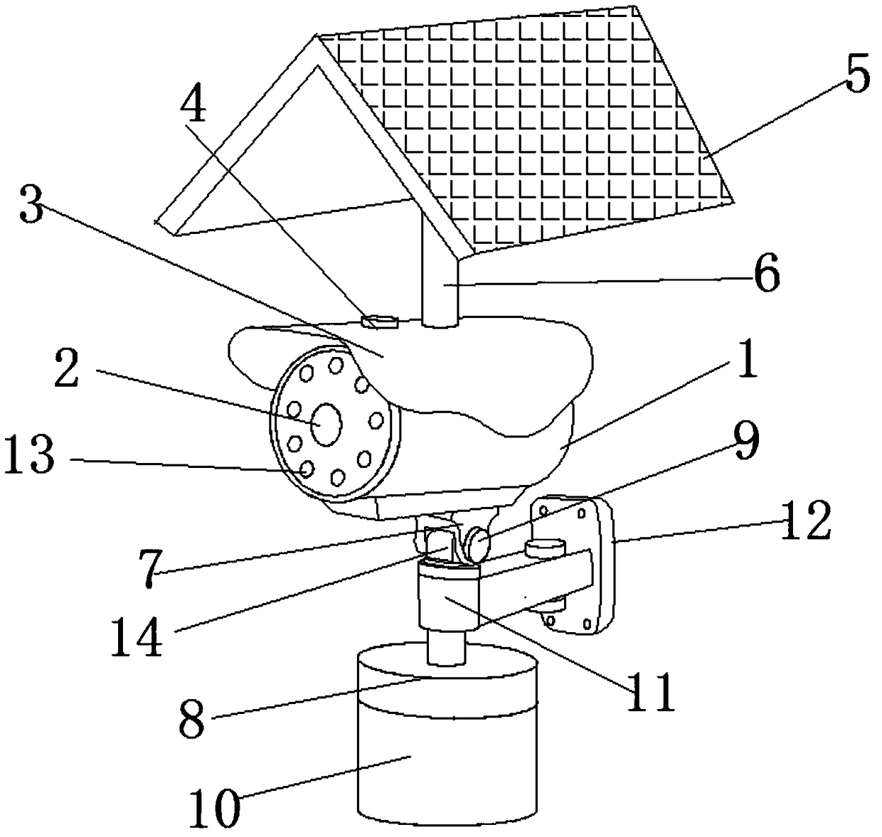
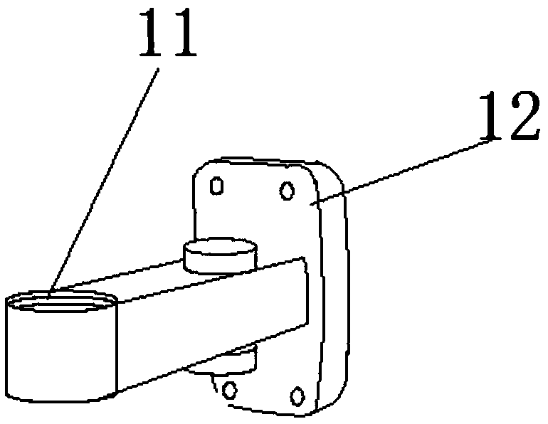
[0018] like Figure 1-2 As shown, a license plate recognition camera with a rotating function includes a camera 1 and a lens 2, and one end of the camera 1 is fixedly provided with a lens 2, and the top of the camera 1 is fixedly connected with a shielding plate 3, and the top of the shielding plate 3 A solar panel 5 is fixedly installed, the top of the camera 1 is fixedly connected with a vertical rotating base 7, the top of the vertical rotating base 7 is fixedly connected with a horizontal rotating rod 14, and the outer side of the horizontal rotating rod 14 is fixedly connected with a sleeve 11, A fixed base 12 is fixedly connected to one side of the casing 11 , a turntable 8 is fixedly connected to the bottom of the horizontal rotating rod 14 ,


PUM


Abstract

The invention discloses a license plate recognition camera with a rotation function. The license plate recognition camera comprises a camera body and a lens, the lens is fixed to one end of the camerabody, a shielding plate is fixedly connected to the top of the camera body, a solar electric board is fixed to the top of the shielding plate, a vertical rotary base is fixedly connected to the top of the camera body, and a horizontal rotary rod is fixedly connected to the top of the vertical rotary base. The vertical rotary base is arranged through the bottom of the camera body, the camera bodycan move vertically under the effect of a second screw to adjust the angle, a gear motor is connected to the horizontal rotary rod and the bottom of a turntable and runs to rotate the horizontal rotary rod through the turntable so that the whole camera body can horizontally rotate, the vision range of recognition and monitoring of the camera body is increased, the solar electric board is arrangedat the top of the shielding plate through a supporting frame and can accumulate a power source for the camera body, the external power supply amount is saved, the environment is protected, and the license plate recognition camera is suitable for wide application and popularization.

Description


Claims


Application Information

Patent Timeline
Owner 嘉兴贝斯特电子技术有限公司
Why Eureka
Try Eureka