Industrial solid waste incineration treatment device

A technology for processing equipment and industrial solid waste, applied in incinerators, combustion methods, combustion types, etc., can solve the problems of easy high temperature injury, unpleasant gas, trouble, etc., and achieve the effect of reducing smoke and dust, simple operation and convenient use

Inactive Publication Date: 2018-06-19
响水新宇环保科技有限公司
View PDF0 Cites 0 Cited by
  • Summary
  • Abstract
  • Description
  • Claims
  • Application Information

AI Technical Summary

Problems solved by technology

[0003] For industrial waste, most of them are solid plastic waste, which will produce a lot of black smoke and unpleasant gas during incineration, and it is n

Method used


Image

  • Industrial solid waste incineration treatment device
  • Industrial solid waste incineration treatment device

Examples


Embodiment Construction

[0015] The following will clearly and completely describe the technical solutions in the embodiments of the present invention with reference to the accompanying drawings in the embodiments of the present invention. Obviously, the described embodiments are only some, not all, embodiments of the present invention.

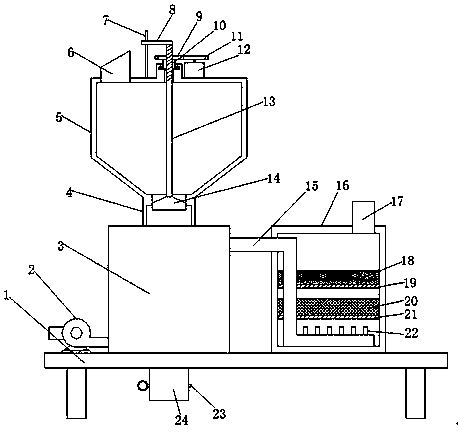
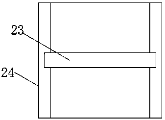
[0016] refer to Figure 1-2 , an industrial solid waste incineration treatment device, comprising a seat plate 1, an incinerator 3 is fixedly installed on the top of the seat plate 1, a connecting cylinder 4 is fixedly installed on the top of the incinerator 3, and a storage tank is fixedly installed on the top of the connecting cylinder 4 5. A motor 12 is fixedly installed on the outer wall of the top of the storage tank 5, the output shaft of the motor 12 is fixedly equipped with a first gear 11, the outer wall of the top of the storage tank 5 is rotatably installed with a rotating shaft 10, and the top of the rotating shaft 10 is fixedly installed with a first gear.


PUM


Abstract

The invention discloses an industrial solid waste incineration treatment device which comprises a seat plate, wherein an incinerator is fixedly arranged on the top end of the seat plate; a connectingcylinder is fixedly arranged on the top end of the incinerator; a storage tank is fixedly arranged on the top of the connecting cylinder; a motor is fixedly mounted on an outer wall on the top of thestorage tank; a first gear is fixedly arranged on an output shaft of the motor; a rotating shaft is rotationally arranged on an outer wall of the top of the storage tank; a second gear is fixedly arranged on the top of the rotating shaft; a threaded hole is formed in an axis position of the second gear and the rotating shaft; the threaded hole runs through a screw; the first gear and the second gear are meshed with each other; a guide plate is fixedly arranged at one end of the screw; a guide rod is fixedly arranged on an outer wall of the top of the storage tank; the guide rod penetrates through the guide plate and is connected with the guide plate in a sliding manner; the other end of the screw extends to the storage tank; and a stopper is fixedly arranged at the other end of the screw.The industrial solid waste incineration treatment device disclosed by the invention is reasonable in design structure, simple in operation and convenient to use, the feeding problem during incineration can be solved, and the smoke dust problem is effectively reduced.

Description


Claims


Application Information

Patent Timeline
Owner 响水新宇环保科技有限公司
Why Eureka
Try Eureka