Local dynamic migration method and control system based on Docker container technology

A docker container and dynamic migration technology, applied in the field of cloud computing, can solve problems such as waste of computing resources, waste of resources, uncertainty of data volume, etc., and achieve the effect of reducing execution time and improving utilization

Pending Publication Date: 2018-06-19
SUZHOU UNIV
View PDF0 Cites 16 Cited by
  • Summary
  • Abstract
  • Description
  • Claims
  • Application Information

AI Technical Summary

Benefits of technology

This patented technique uses Docker (Dynamic Object Layer) techniques for moving data objects across different computers or storage devices efficiently without overloading any resources that could otherwise run slower downstreams. It also includes various technical features such as optimizing memory usage by caching frequently used files instead of relying solely upon static allocation methods like VMware's KVM (Kernelized Virtual Machine). Overall this improves efficiency and performance of computer systems while reducing their overall impact on system architectures.

Problems solved by technology

This patents discuss various technical solutions aim at efficiently managing loads within a Cloud Service Platform when transferring software across boundaries such as isolated zones like edge networks. These techniques include loading partitions onto cores dynamically instead of waiting until all workloads start up again, allowing programmers to focus their efforts more towards specific areas rather than just those where they may get lost altogether. Additionally, these methods allow for unpredictability in terms of hardware configuration and deployment options, making them suitable for use in real world scenarios.

Method used


Image

  • Local dynamic migration method and control system based on Docker container technology
  • Local dynamic migration method and control system based on Docker container technology
  • Local dynamic migration method and control system based on Docker container technology

Examples


Embodiment approach 1

[0049] Embodiment 1. A local dynamic migration method based on Docker container technology described in this embodiment includes the following steps:

[0050] Step 1. According to the periodic collection of the resource usage of each node in the cluster node, monitor the resource usage of each node in the cluster node, and determine whether there is a hot spot. When a hot spot is found, trigger the following steps to start the container migration ;

[0051] Step 2, count the usage parameter volume of different resources integrated by each server in the cluster,

[0052]

[0053] In the formula, mem represents the memory usage rate of the server or container, cpu represents the CPU usage rate, and net represents the bandwidth utilization rate; sort the N servers in the cluster in descending order according to the size of the volume value;

[0054] According to the formula of the parameter volume, it can be determined that the higher the utilization rate of the resource, the la

Embodiment approach 2

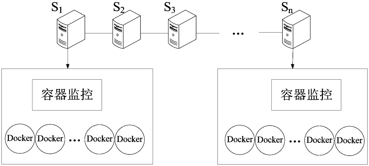
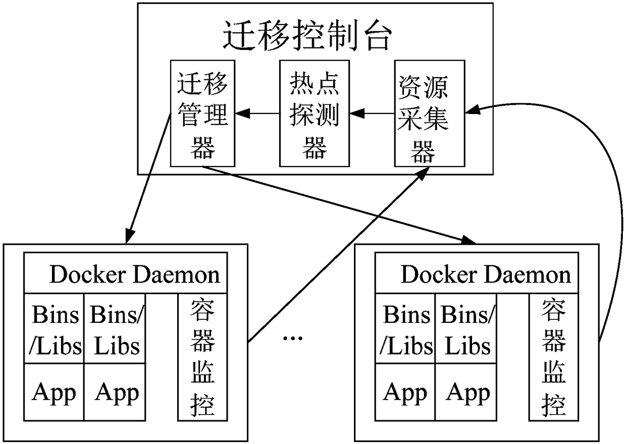
[0078] Implementation mode two, see figure 1 with 2 This embodiment will be described. What this embodiment describes is a local dynamic migration control system based on Docker container technology, the control system includes cluster nodes, and the control system also includes a migration control unit; each server node includes a container monitoring unit and a plurality of Docker container;

[0079] The container monitoring unit is used to monitor the resource usage status of all Docker containers in the server node;

[0080] The migration control unit includes a migration manager, a hotspot detector and a resource collector, wherein:

[0081] The resource collector is used to collect the resource usage status of the Docker container obtained by the container monitoring unit in all server nodes; it is also used to generate a resource usage configuration file for each container; it is also used to generate an integrated resource usage configuration for each server document;


PUM


Abstract

The invention provides a local dynamic migration method and control system based on a Docker container technology, and belongs to the technical field of cloud computing. The problem of resource wastein an existing container migration technology is solved. The method determines the appearing of an overload server and triggers container migration according to the node resource usage rate and the predicted resource usage rate in the last n sampling periods; for the selection of a to-be-migrated container in the overload server, a container with large total usage rate and smaller internal storageis selected firstly to achieve the effect of balancing load while reducing migration overhead. For the selection of a target server, firstly enough available resources in the target server are ensured. For the case where a new container is generated in the migration process and the target server is overloaded caused by paralleling, it means that there is no server which can accommodate the container in all servers in the cluster, so that there is no need to migrate the container and replace the to-be-migrated container. The local dynamic migration method and control system improve resource utilization and reduce task execution time.

Description


Claims


Application Information

Patent Timeline
Owner SUZHOU UNIV
Why Eureka
Try Eureka