Water flow electricity generating device

A water flow power generation and generator technology, applied in hydropower, engine components, machines/engines, etc., can solve problems such as rising power generation costs, environmental pollution, and coal shortages, and achieve the effects of reducing power generation costs and protecting the environment

Inactive Publication Date: 2018-06-22
张建洲
View PDF10 Cites 2 Cited by
  • Summary
  • Abstract
  • Description
  • Claims
  • Application Information

AI Technical Summary

Problems solved by technology

[0002] At present, my country's power generation mainly relies on coal thermal power generation, but the cu

Method used


Image

  • Water flow electricity generating device
  • Water flow electricity generating device

Examples


Embodiment Construction

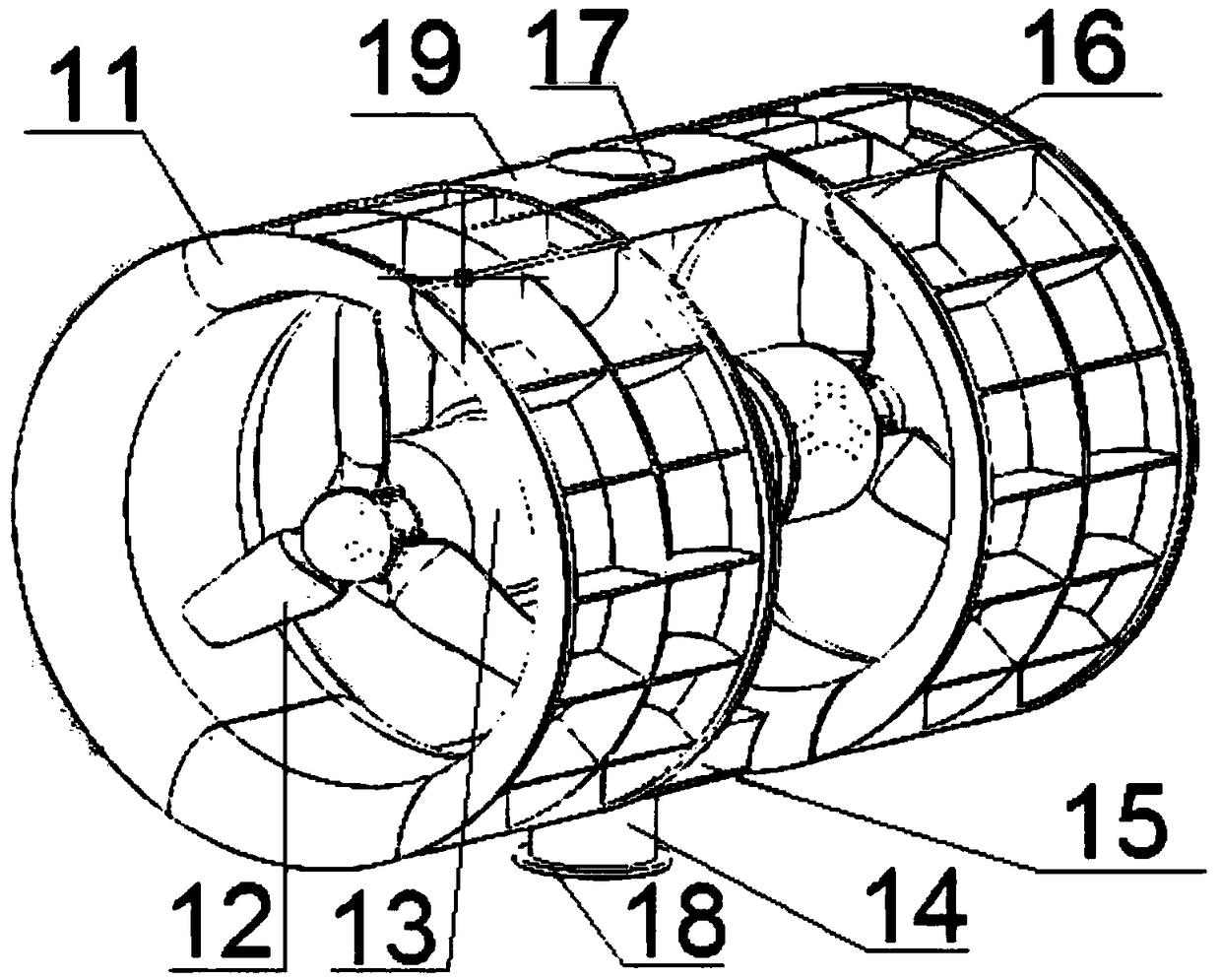
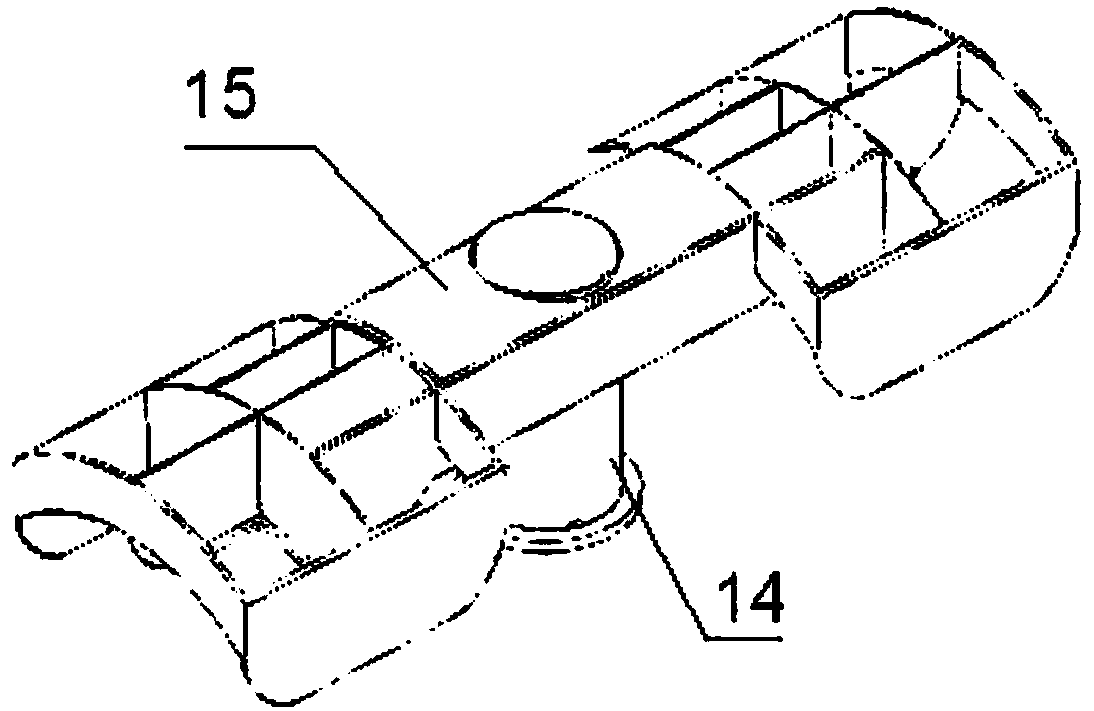
[0026] The embodiment of the present invention discloses a water flow power generation device, which uses flowing river water or seawater to generate power. Compared with coal power generation commonly used in the prior art, the power generation cost can be reduced, and it is pollution-free, which is beneficial to environmental protection.

[0027] The following will clearly and completely describe the technical solutions in the embodiments of the present invention with reference to the accompanying drawings in the embodiments of the present invention. Obviously, the described embodiments are only some, not all, embodiments of the present invention. Based on the embodiments of the present invention, all other embodiments obtained by persons of ordinary skill in the art without making creative efforts belong to the protection scope of the present invention.

[0028] see Figure 1-Figure 2 , the embodiment of the present invention provides a water current power generation device, w


PUM


Abstract

The invention discloses a water flow electricity generating device. The water flow electricity generating device comprises a base, a water gathering cover, a four-way connector and an electricity generator, wherein the base is fixed on a river bed or a sea bed through foundation spud piles; the upper part of the water gathering cover is fixedly provided with a fixed support; a lower channel in thevertical direction of the four-way connector is connected with the base, and an upper channel is fixed to the fixed support; the electricity generator is located in the water gathering cover, and theelectricity generator is fixed to the four-way connector along a channel in the horizontal direction; and an impeller is mounted on the electricity generator. The water flow electricity generating device utilizes flowing river water or sea water to generate electricity, and compared with a common coal-fired electricity generating mode in the prior art, does not need raw materials, such as coal, so that the electricity generating cost can be reduced, no pollution is caused, and environmental protection is facilitated.

Description


Claims


Application Information

Patent Timeline
Owner 张建洲
Why Eureka
Try Eureka