Clamping device and hydraulic clamping device

A clamping device and clamping technology, used in workpiece clamping devices, manufacturing tools, etc., can solve the problems of complex structure, inability to precisely control clamping force, and low reliability.

Pending Publication Date: 2018-06-29
重庆世中星机电设备有限公司
View PDF6 Cites 0 Cited by
  • Summary
  • Abstract
  • Description
  • Claims
  • Application Information

AI Technical Summary

Benefits of technology

This patented technology allows for effective gripping on difficultly shaped objects with hydrous materials like water instead of pneumatic ones that require external energy sources such as compressed gas cylinders.

Problems solved by technology

The technical problem addressed by this patented design is how to create an efficient and reliable way for holding down small parts while still allowing them to be accurately controlled with precision.

Method used


Image

  • Clamping device and hydraulic clamping device
  • Clamping device and hydraulic clamping device
  • Clamping device and hydraulic clamping device

Examples


Embodiment 1

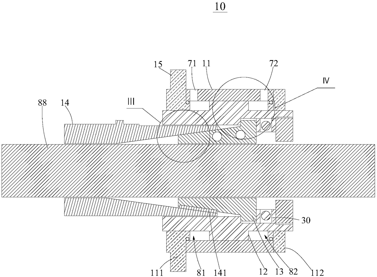
[0066] This embodiment provides a clamping device 10, which is different from the existing clamps. The clamping device 10 can use hydraulic pressure or air pressure as power to effectively clamp the clamped object.

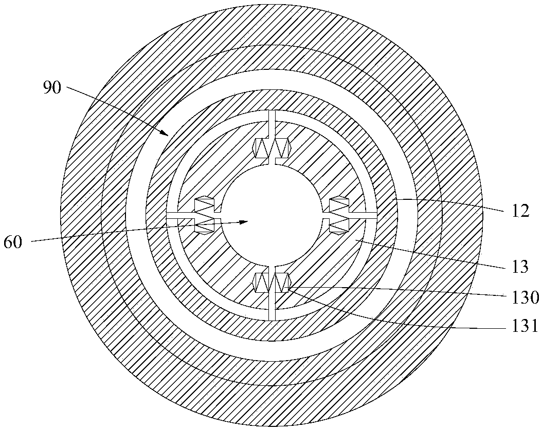
[0067] Please refer to figure 1 and figure 2 , figure 1 It shows the specific structure of the clamping device 10 in the first viewing angle in this embodiment. figure 2 It shows the specific structure of the clamping device 10 in the second viewing angle in this embodiment.

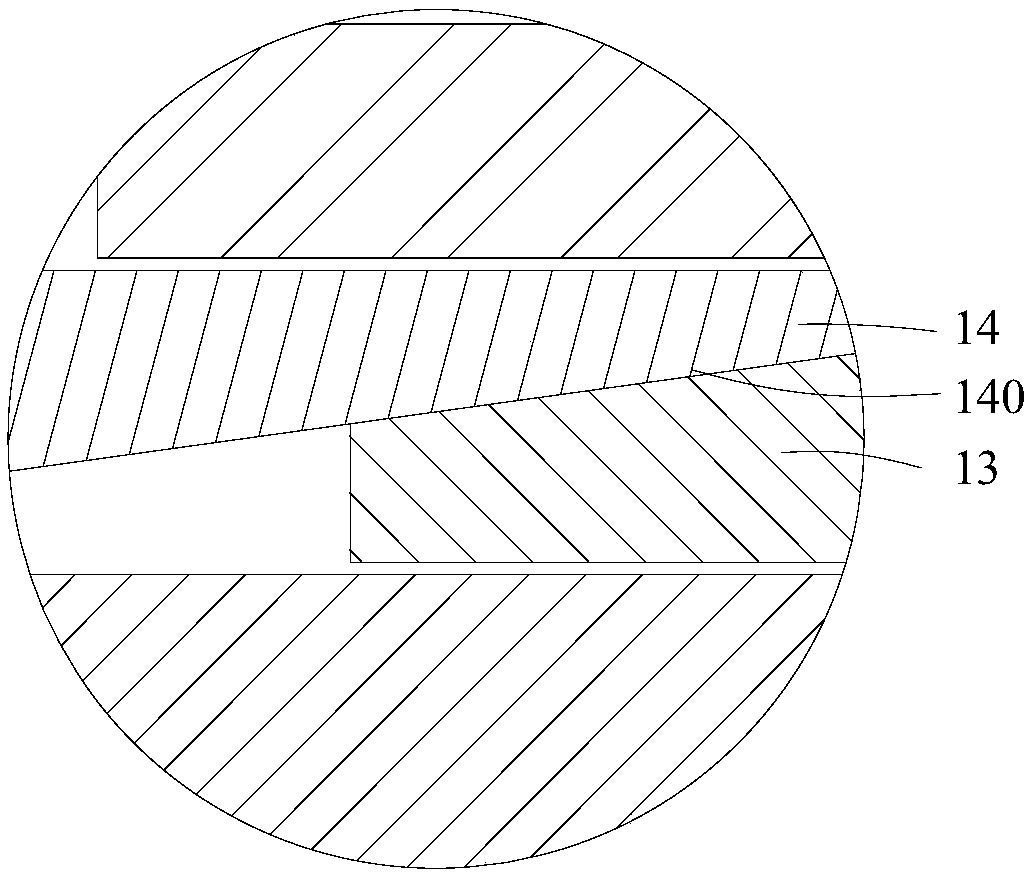
[0068] The clamping device 10 is suitable for both pneumatic and hydraulic driving methods. Specifically, the clamping device 10 includes a base 11 , a sliding sleeve 12 , clamping slips 13 and a fixed taper sleeve 14 .

[0069] The base body 11 has opposite first end 111 and second end 112 , inside the base body 11 there is a movable cavity 90 , and the movable cavity 90 runs through the first end 111 and the second end 112 .

[0070] The sliding sleeve 12 is slidably disposed in the mov


PUM


Abstract

The invention discloses a clamping device and a hydraulic clamping device and relates to the technical field of clamps. The clamping device comprises a base body, a sliding sleeve, clamping slips anda fixing taper jacket. The base body is internally provided with a movable cavity. The sliding sleeve is slidably arranged inside the movable cavity. A plurality of clamping slips are movably arrangedin a transmission space, and every two adjacent clamping slips are elastically connected. The plurality of clamping slips are in transmission connection with the sliding sleeve. The inner wall, closeto the clamping slips, of the fixing taper jacket is provided with a taper surface which is inclined in a direction from a first end to a second end; and the outer walls of the clamping slips lean against the taper surface. The clamping device differs from an existing clamp and can be used for effectively clamping a clamped part by using hydraulic pressure or air pressure as power.

Description


Claims


Application Information

Patent Timeline
Owner 重庆世中星机电设备有限公司
Why Eureka
Try Eureka