Carrying device and aircraft

A technology for carrying devices and aircraft, applied in aircraft parts, transportation and packaging, non-rotational vibration suppression, etc., can solve problems such as data synchronization, and achieve the effect of avoiding abnormal functions, ensuring flight attitude and flight stability.

Pending Publication Date: 2018-07-10
ZEROTECH (SHENZHEN) INTELLIGENCE ROBOT CO LTD
View PDF8 Cites 0 Cited by
  • Summary
  • Abstract
  • Description
  • Claims
  • Application Information

AI Technical Summary

Benefits of technology

This patented technology allows an airplanes with bearings devices built into them to prevent collisions without adding extra hardware or requiring modifications during their manufacture process. It achieves this by creating connections within the bearings themselves rather than just connecting these structures together. By doing things like setting up tolerances, the equipment becomes more accurate over its lifetime compared to previous designs. Additionally, there may exist other features such as sensors attached to the bearer itself (such as cameras) allowing precise measurements from different angles around the world). Overall, this innovation simplifies the way we install the bearers inside our wings while maintaining high levels of accuracy.

Problems solved by technology

The technical problem addressed in this patented text relates to improving the accuracy and consistency between two different types of images captured through an optical system used for navigation or surveying purposes (Binocular Lenses). This can lead to improved stability when flying over uneven surfaces such as snowy roads without causing instability issues like poor visibility caused by shake waves that may occur due to turbulence or other factors associated with airplanes traveling at high speeds.

Method used


Image

  • Carrying device and aircraft
  • Carrying device and aircraft
  • Carrying device and aircraft

Examples


Embodiment Construction

[0056] In order to make the objectives, technical solutions and advantages of the present invention more clearly understood, the carrying device and the aircraft of the present invention will be further described in detail below through embodiments and in conjunction with the accompanying drawings. It should be understood that the specific embodiments described herein are only used to explain the present invention, but not to limit the present invention.

[0057]In describing the present invention, it should be understood that the terms "center", "longitudinal", "transverse", "length", "width", "thickness", "upper", "lower", "front", " Back", "Left", "Right", "Vertical", "Horizontal", "Top", "Bottom", "Inner", "Outer", "Axial", "Radial", "Circumferential", etc. The indicated orientation or positional relationship is based on the orientation or positional relationship shown in the drawings, and is only for the convenience of describing the present invention and simplifying the des


PUM


Abstract

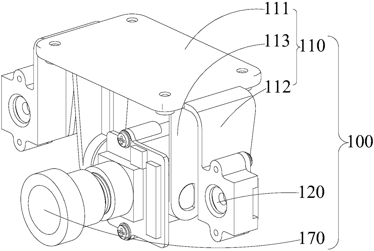
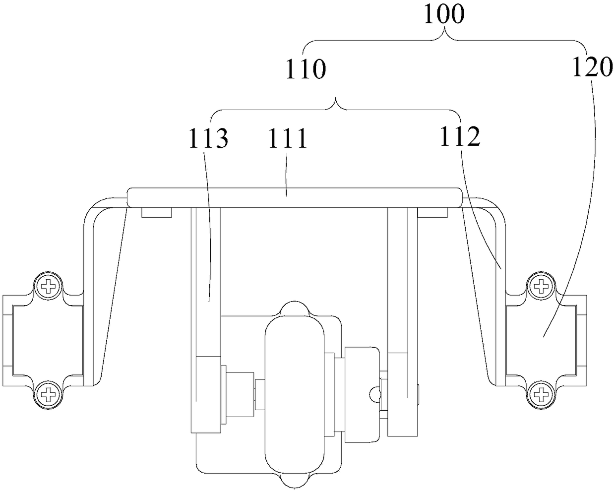
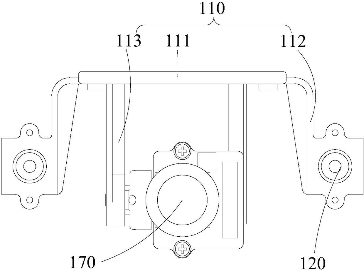
The invention provides a carrying device. The carrying device is used for being mounted on an aircraft body of an aircraft and comprises a gimbal on which an obstacle-avoidance positioning assembly and an inertial measuring assembly of the aircraft are mounted and a shock absorbing assembly mounted on the gimbal, wherein the gimbal is mounted on the aircraft body through the shock absorbing assembly. The obstacle-avoidance positioning assembly and the inertial measuring assembly are rigidly connected through the gimbal, and the obstacle-avoidance positioning assembly and the inertial measuringassembly use the same shock absorbing assembly for shock avoidance, so as to ensure that the data fed back from the obstacle-avoidance positioning assembly and the data fed back from the inertial measuring assembly can be synchronized accurately, to effectively solve the problem that the feedback data of the obstacle-avoidance positioning assembly and the feedback data of the inertial measuring assembly are inconsistent, to ensure the flight attitude of the aircraft, to enable the aircraft to fly smoothly and to improve the satisfaction of users during use. The invention also provides the aircraft.

Description


Claims


Application Information

Patent Timeline
Owner ZEROTECH (SHENZHEN) INTELLIGENCE ROBOT CO LTD
Why Eureka
Try Eureka