Minitype photoelectric sensor

A photoelectric sensor and miniature technology, applied in the field of photoelectric sensors, can solve the problems of easy breakage of optical fibers, small size, high price, etc., to achieve the effect of improving signal-to-noise ratio and anti-interference ability, small size, and improving test distance

Active Publication Date: 2018-07-13
INTELLISENSEXIAMEN MICROELECTRONICS LTD
View PDF12 Cites 1 Cited by
  • Summary
  • Abstract
  • Description
  • Claims
  • Application Information

AI Technical Summary

Problems solved by technology

Due to the small size of the optical fiber, there is a certain degree of bendability, and the optical fiber can be used to form a miniature photoelectric sensor with a diameter of only 3mm in the transmitting and receiving part, such as the small optical fiber sensor series of Japanese Keyence, Japanese Omron and other companies; but the optical fiber is easy to break, and the optical fiber It also needs to be connected to a fiber amplifier for amplification and signal processing, and t

Method used


Image

  • Minitype photoelectric sensor
  • Minitype photoelectric sensor
  • Minitype photoelectric sensor

Examples


Embodiment Construction

[0038] The following will clearly and completely describe the technical solutions in the embodiments of the present invention with reference to the accompanying drawings in the embodiments of the present invention. Obviously, the described embodiments are only some, not all, embodiments of the present invention. Based on the embodiments of the present invention, all other embodiments obtained by persons of ordinary skill in the art without creative efforts fall within the protection scope of the present invention.

[0039] It should be noted that, in the case of no conflict, the embodiments of the present invention and the features in the embodiments can be combined with each other.

[0040] The present invention will be further described below in conjunction with the accompanying drawings and specific embodiments, but not as a limitation of the present invention.

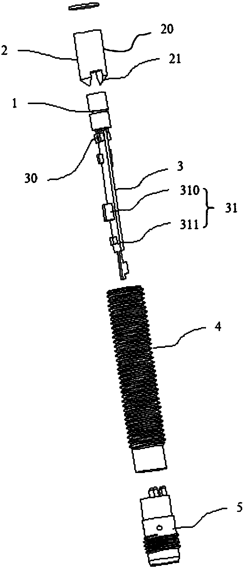
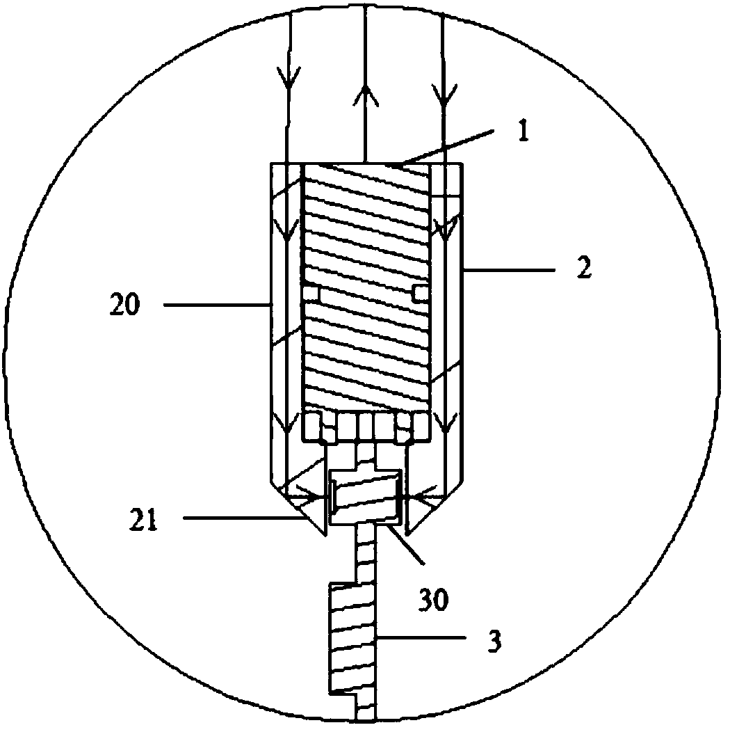
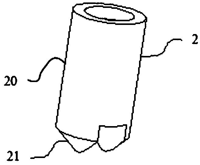
[0041] The present invention includes a miniature photoelectric sensor, wherein the miniature photoelectric sensor


PUM


Abstract

The invention discloses a minitype photoelectric sensor. The minitype photoelectric sensor comprises a light source device, an optical prism and a circuit board. The light source device is installed in the optical prism and electrically connected with the circuit board. The light source device is used for emitting a light beam. The circuit board is positioned below the light source device. The upper part of the optical prism forms an optical receiving lens which is used for collecting the reflected light beam. The lower part of the optical prism forms an optical condensing lens which is used for collecting the light beam received by the optical receiving lens to the circuit board. The circuit board is provided with a photoelectric receiving tube and a signal processing circuit. The photoelectric receiving tube is installed on a position, closest to the light source device, on the circuit board. The signal processing circuit is connected with the photoelectric receiving tube through thecircuit board. The beneficial effect is that the volume is tiny, the same optical prism is used for finishing the sending and the receiving of the light beam, a measuring distance of the photoelectric sensor is further improved, and a main working circuit of the photoelectric sensor is used, so the signal to noise ratio and the disturbance resisting capacity of the sensor are improved.

Description


Claims


Application Information

Patent Timeline
Owner INTELLISENSEXIAMEN MICROELECTRONICS LTD
Why Eureka
Try Eureka