Laser fluorescence excitation illumination device

A technology for exciting fluorescence and lighting devices, applied in lighting devices, lighting device parts, lighting device cooling/heating devices, etc. Defective, improve heat exchange efficiency, increase the effect of heat dissipation area

Pending Publication Date: 2018-07-17
MIANYANG POWERFUL JETFLY TECH CO LTD
View PDF0 Cites 0 Cited by
  • Summary
  • Abstract
  • Description
  • Claims
  • Application Information

AI Technical Summary

Benefits of technology

This patented technology improves the performance (efficiency), durability, safety, etc of an LED lamp used for illumination purposes by efficiently utilizing energy produced during operation without causing excessive temperatures or damage on other components within the system. By arranging the lasers around the fluorocalton instead of directly behind it, they act like lamps while still emiting their full brightness when turned off. Additionally, this design allows for quick cool down after use, increasing the lifespan of the materials involved. Overall, these technical improvements enhance the overall effectiveness and longevity of the LED lamp's functioning.

Problems solved by technology

The technical problem addressed in this patented technology relates to improving the performance and lifetimes of conventional red lasers excited from yellow phosphors due to their poor thermal characteristics caused by these compounds themselves during operation.

Method used


Image

  • Laser fluorescence excitation illumination device
  • Laser fluorescence excitation illumination device
  • Laser fluorescence excitation illumination device

Examples


Embodiment Construction

[0021] The content of the invention will be described below in conjunction with the drawings and embodiments.

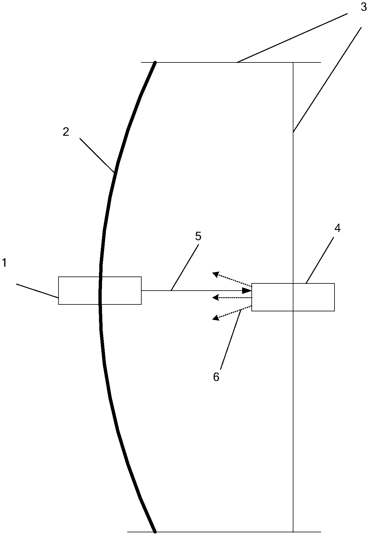
[0022] figure 1 It is a schematic diagram of the lighting device of the present invention, which consists of a laser light source (1), a reflective bowl (2), a support mechanism (3), and a fluorescent excitation device (4), wherein the support structure (3) is used to fix the laser light source (1) , a reflective bowl (2), a fluorescent excitation device (3); the laser light source (1) is located at the bottom of the reflective bowl (2), and projects a laser beam (5) to the fluorescent excitation device (3); the fluorescent excitation device (4) is located in the reflective bowl (2) At the focal point, after receiving the laser beam (5) projected by the laser light source (1), the fluorescence (6) is radiated outward; the fluorescence (6) is figure 1 The dotted line with the arrow in the middle; the radiated fluorescent light (6) reaches the bottom of the reflective bo


PUM


Abstract

In order to overcome the problem of incapability of timely dissipating accumulated heat efficiently due to continuous work of a fluorescent material in a traditional fluorescent illumination light source, the invention discloses a laser fluorescence excitation illumination device. The device consists of a laser light source, a reflecting bowl, a support mechanism and a fluorescence excitation device, wherein the fluorescence excitation device consists of a fluorescent turntable, a heat sink and a heat dissipating fin. The laser fluorescence excitation illumination device adopts an interval excitation mode, so that the fluorescent material is located in an intermittent working state to prevent centralized heat caused by continuous work and to improve the heat exchange efficiency. The fluorescent turntable and the heat sink are made of red copper materials with excellent heat conductivity; and heat generated by an excitation end can be quickly transferred to a back end heat dissipating structure. The back end heat dissipating structure is a of a fine structure for increasing the heat dissipating area. Heat conducting silicone grease is coated in each connected place in the device toprevent bad heat conduction caused by assembly gaps. The laser fluorescence excitation illumination device can effectively improve the heat dissipation efficiency of the fluorescent illumination device and prolong the service life of the fluorescent material.

Description


Claims


Application Information

Patent Timeline
Owner MIANYANG POWERFUL JETFLY TECH CO LTD
Why Eureka
Try Eureka