Laser ranging calibration device and calibration method thereof

A calibration device and laser ranging technology, applied in the field of measurement and calibration, can solve the problems of reduced applicability of the laser ranging system, and achieve the effects of low cost, satisfactory accuracy, and simple operation

Active Publication Date: 2018-08-17
SHENZHEN KYLE OPTICS TECH CO LTD
View PDF6 Cites 29 Cited by
  • Summary
  • Abstract
  • Description
  • Claims
  • Application Information

AI Technical Summary

Benefits of technology

This patented technology allows us to accurately measure distance by measuring how well it's reflected or shaded from lighting sources like LED lights. By calculating these distances based on their specific characteristics, we aimed at create devices that work with them effectively without requiring expensive equipment.

Problems solved by technology

This patented describes how accurate measurements can occur when there are multiple reflections from identical surfaces that have similar levels of light absorption (reflectance). However, if these reflections come back into their original form after being exposed to specific wavelengths of electromagnetic radiation they may interfere destructively due to constructive/destructive effects such as heating or cooling processes. To solve this problem, it suggests adding extra layers made up of materials called mirror coatings onto each surface separately. These coating layers help reduce unwanted interactions during exposure and improve the quality of the resulting image obtained through detection techniques like optical coherence tomography.

Method used


Image

  • Laser ranging calibration device and calibration method thereof
  • Laser ranging calibration device and calibration method thereof
  • Laser ranging calibration device and calibration method thereof

Examples


Embodiment 1

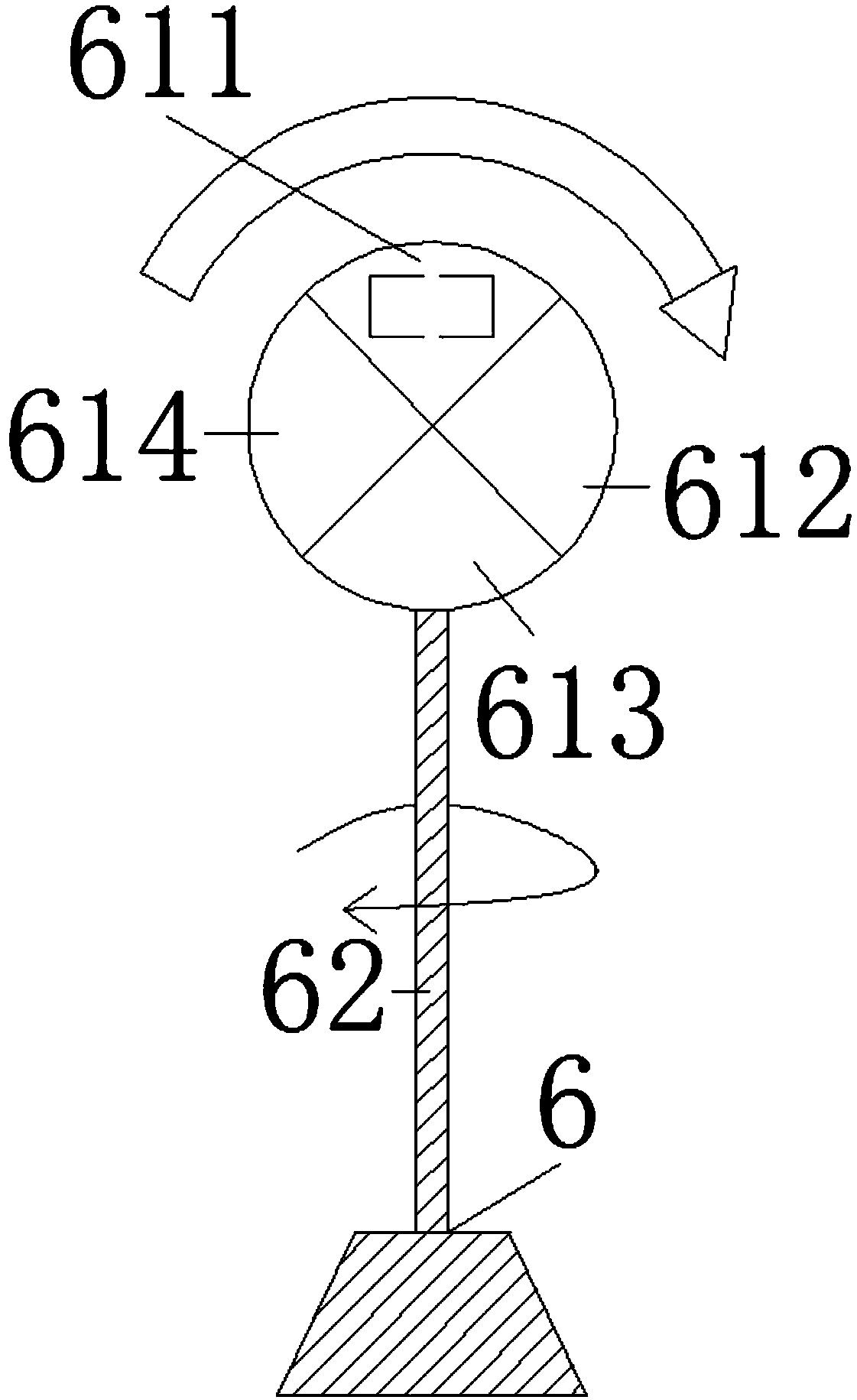
[0039] Such as Figure 1-4 As shown, the present embodiment provides a laser ranging calibration device including a test bench 1. First, a laser transmitter 2, a laser receiver 3, a data processor 4 and a reflector controller 5 are fixedly installed on the test bench 1, and then the One side of the test bench is provided with a track 7 and a reflector base 6 . A reflector 61 is attached to a central axis 62 of the reflector base 6 .

[0040] The input port of the laser transmitter is connected to the data processor, and is used to receive the electric excitation control signal transmitted by the data processor, and the output port of the laser transmitter is set against the reflector; the laser transmitter 2 for emitting laser signals to the reflection plate 61. Specifically, the laser transmitter includes a control circuit, an optical path and a laser.

[0041] The laser receiver is arranged in the area covered by the reflected laser of the reflector, the laser receiver is co


PUM


Abstract

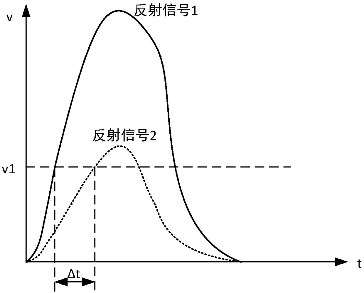
The invention belongs to the technical field of measurement and calibration, and discloses a laser ranging calibration device. The laser ranging calibration device comprises an experiment table, a laser emitter, a laser receiver, a data processor and a reflector controller are arranged on the experiment table, and the data processor is used for calculating the time difference between the moment when the laser emitter emits a laser signal and the moment when the laser receiver receives the reflected laser signal, calculating measurement distances and calibration values and then saving the corresponding calibration values. The invention further discloses a calibration method using the laser ranging calibration device. By means of the laser ranging calibration device, according to different reflectivities and different incidence angles, corresponding calibration values can be calculated and then saved, multiple groups of calibration data can be obtained, and in actual measurement, all thesaved data can be used for calibration.

Description


Claims


Application Information

Patent Timeline
Owner SHENZHEN KYLE OPTICS TECH CO LTD
Why Eureka
Try Eureka