Automatic feeding manipulator of punching machine

A technology of automatic feeding and manipulators, applied in manipulators, metal processing equipment, feeding devices, etc., can solve problems that affect processing efficiency, complex installation, high cost, etc., and achieve improved processing efficiency, improved efficiency, good continuity and reliability sexual effect

Active Publication Date: 2018-08-24
王震林
View PDF6 Cites 5 Cited by
  • Summary
  • Abstract
  • Description
  • Claims
  • Application Information

AI Technical Summary

Problems solved by technology

In this processing method, if there is only one manipulator, there will be idle processing for a certain period of time during the loading and unloading process.
However, if two manipulators are configured, the space required for the two mani

Method used


Image

  • Automatic feeding manipulator of punching machine
  • Automatic feeding manipulator of punching machine
  • Automatic feeding manipulator of punching machine

Examples


Embodiment Construction

[0028] The following will clearly and completely describe the technical solutions in the embodiments of the present invention with reference to the accompanying drawings in the embodiments of the present invention. Obviously, the described embodiments are only some, not all, embodiments of the present invention. Based on the embodiments of the present invention, all other embodiments obtained by persons of ordinary skill in the art without making creative efforts belong to the protection scope of the present invention.

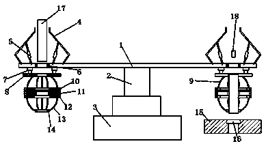
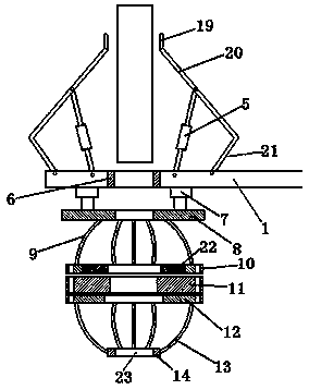
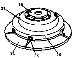
[0029] see Figure 1-3 , the present invention provides a technical solution: an automatic feeding manipulator for a punching machine, which includes an indexing rotating disk 1, a driving shaft 2, a connecting base 3, a mechanical claw grabbing component and a stamping clamping component, and the connecting base 3 A rotary driver is used to connect the driving shaft 2, and the driving shaft 2 is connected to the center of the indexing rotating disk 1, so as to d


PUM


Abstract

The invention discloses an automatic feeding manipulator of a punching machine. Through the automatic feeding manipulator, the machining efficiency of the punching machine can be greatly improved; thefeeding and discharging efficiency is improved through an indexing rotating method; during machining, workpieces cannot get away from the manipulator, the machining precision and the machining efficiency are improved. During machining and feeding, when the punching machine conducts feeding and punching, mechanical gripper grabbing assemblies grabs the workpieces, and the lower ends of the workpieces are located in workpiece passing holes of an indexing rotary disk. The indexing rotary disk rotates, the workpieces are moved to the locations under punch pins, feed cylinders descend to conduct feeding to make the lower end of a punching and clamping assembly be located to a punching bottom die, and then the corresponding mechanical gripper grabbing assembly loosens the corresponding workpiece, the workpiece falls into the corresponding stamping and clamping assembly and clamped by the stamping and clamping assembly, and then the workpiece is subjected to stamping or punching through thecorresponding punch pin. After completion of machining, the indexing rotary disk rotates to drive the punching and clamping assemblies to rotate to the discharging position, and the punching and clamping assemblies loosen the workpieces to complete discharging.

Description


Claims


Application Information

Patent Timeline
Owner 王震林
Why Eureka
Try Eureka