Optical imaging device capable of positioning projection

An optical imaging and positioning technology, applied in optics, optical components, transportation and packaging, etc., can solve problems such as not meeting market demand, restricting driver's driving posture, and not applicable to ARHUD

Active Publication Date: 2018-08-28
SITRONIX TECH CORP
View PDF9 Cites 1 Cited by
  • Summary
  • Abstract
  • Description
  • Claims
  • Application Information

AI Technical Summary

Problems solved by technology

[0005] Although the position of the first projection area A1 can be changed to adjust the image height by adjusting the angle of the optical projection member M1, for example, Chinese Patent Application Publication No. CN106461948A discloses a similar HUD image adjustment method, but adjusting the optical projection member The angle of M1 will also change the angle at which the optical projection part M1 projects the image on the windshield W. This adjustment

Method used


Image

  • Optical imaging device capable of positioning projection
  • Optical imaging device capable of positioning projection
  • Optical imaging device capable of positioning projection

Examples


Embodiment Construction

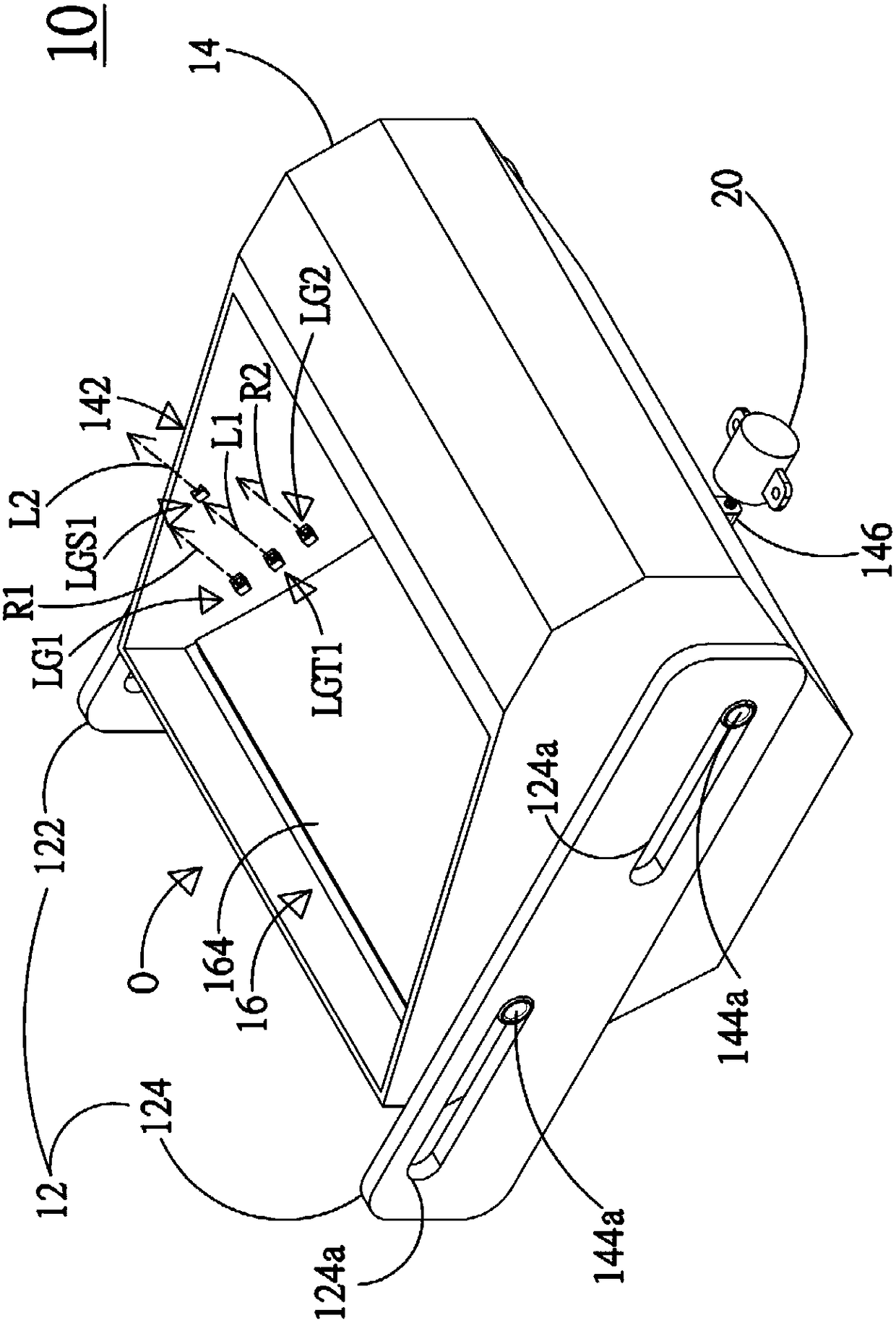
[0127] see Figure 3A to Figure 3D , which are a perspective view, another perspective view, a side view and a cross-sectional view of an embodiment of the optical imaging device of the present invention. Such as Figure 3A to Figure 3D As shown, the optical imaging device 10 of this embodiment includes a casing 14 and an optical projection assembly 16. The housing 14 of this embodiment is provided with an opening O, and a first first connecting member 142a is provided on a first side wall 142 of the housing 14, and a second connecting member 142a is provided on a second side wall 144 of the housing 14. 144a, the optical projection assembly 16 of this embodiment is provided with a mirror 162 and an optical projection element 164, but not limited thereto.

[0128] The casing 14 is arranged on the moving mechanism 12, and the moving mechanism 12 includes a first moving part 122 and a second moving part 124, wherein the first moving part 122 is arranged on the outside of the first


PUM


Abstract

An optical imaging device capable of positioning projection comprises a housing. A first positioning light-emitting component and a second positioning light-emitting component are arranged at a side wall of the housing, and respectively generate a first positioning light and a second positioning light. For a driver, the first positioning light and the second positioning light have a same angle ofreflection at only one display area to enable the optical imaging device to position the field of view of the driver and display an optical image corresponding to the field of view of the driver.

Description


Claims


Application Information

Patent Timeline
Owner SITRONIX TECH CORP
Why Eureka
Try Eureka