Automobile plastic vacuum tank qualification detecting device
A technology of detection device and vacuum tank, which is applied to measurement devices, instruments, sorting and other directions, can solve the problems of single function of detection equipment, high labor input cost, low detection accuracy, etc., and achieves enhanced safety performance and convenient operation. , the effect of simple structure
- Summary
- Abstract
- Description
- Claims
- Application Information
AI Technical Summary
Problems solved by technology
Method used
Image

Examples
Example Embodiment
[0026] Example 1
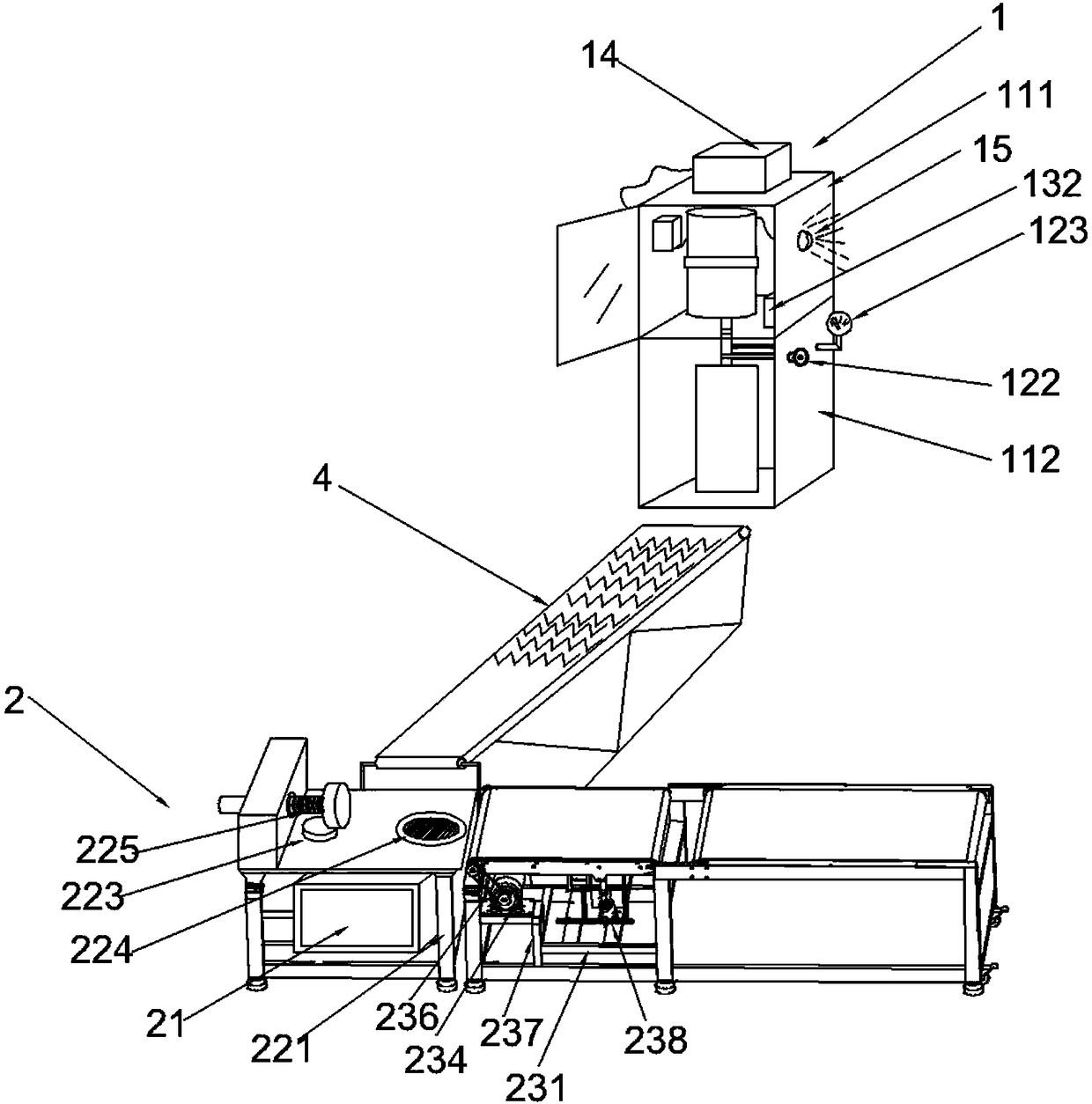
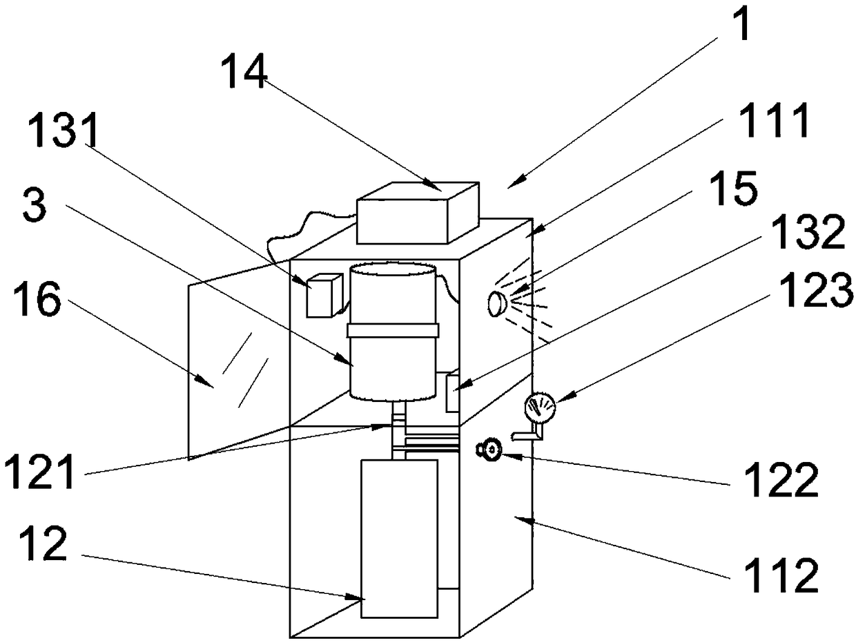
[0027] Example 1 discloses a qualified inspection device for automotive plastic vacuum tanks, such as figure 1 As shown, including a vacuum tank air tightness detection device 1 and a vacuum tank quality inspection machine 2, the vacuum tank air tightness detection device 1 and the vacuum tank quality inspection machine 2 are connected by a conveyor belt 4; Figure 2-3 As shown, the vacuum tank air tightness detection device includes an upper box body 111 and a lower box body 112. The upper box body 111 and the lower box body 112 are fixedly connected. The air tightness detection device also includes a compressed air storage tank 12 and two gas The detectors 131 and 132, the compressed air storage tank 12 are fixedly installed in the lower box 112, and the gas detectors 131 and 132 are placed in the upper box 111. The gas detector 131 is installed on the upper part of the upper box 111. 132 is installed in the lower part of the upper box 111. The joint 121 of the
Example Embodiment
[0032] Example 2
[0033] Embodiment 2 discloses a qualified inspection device for automotive plastic vacuum tanks, including a vacuum tank air tightness inspection device 1 and a vacuum tank quality inspection machine 2, a vacuum tank air tightness inspection device 1 and a vacuum tank quality inspection machine 2 through a conveyor belt 4 connection;
[0034] The vacuum tank air tightness detection device 1 includes an upper tank body 111 and a lower tank body 112, the upper tank body 111 and the lower tank body 112 are fixedly connected, and the air tightness detection device also includes a compressed air storage tank 12 and two gas detectors 131 and 132, the compressed air storage tank 12 is fixedly installed in the lower box 112, the gas detectors 131 and 132 are placed in the upper box 111, and the gas detector 131 is installed on the upper part of the upper box 111, and the gas detector 132 is installed In the lower part of the upper box 111. The joint 121 of the compressed
Example Embodiment
[0039] Example 3
[0040] Embodiment 3 discloses a qualified inspection device for automotive plastic vacuum tanks, including a vacuum tank air tightness inspection device 1 and a vacuum tank quality inspection machine 2, a vacuum tank air tightness inspection device 1 and a vacuum tank quality inspection machine 2 through a conveyor belt 4 connection;
[0041] The vacuum tank air tightness detection device 1 includes an upper box body 111 and a lower box body 112. The upper box body 111 and the lower box body 112 are fixedly connected. The air tightness detection device also includes a compressed air storage tank 12 and two gas detectors. 131 and 132, the compressed air storage tank 12 is fixedly installed in the lower box 112, the gas detectors 131 and 132 are placed in the upper box 111, and the gas detector 131 is installed on the upper part of the upper box 111, and the gas detector 132 is installed In the lower part of the upper box 111. The joint 121 of the compressed air sto
PUM
 Abstract
Description
Claims
Application Information
 - R&D Engineer
- R&D Manager
- IP Professional
- Industry Leading Data Capabilities
- Powerful AI technology
- Patent DNA Extraction
Browse by: Latest US Patents, China's latest patents, Technical Efficacy Thesaurus, Application Domain, Technology Topic.
© 2024 PatSnap. All rights reserved.Legal|Privacy policy|Modern Slavery Act Transparency Statement|Sitemap