Energy equipment modeling method, device and equipment and energy station scheduling method, device and equipment

A modeling method and energy station technology, applied in resources, design optimization/simulation, instruments, etc., can solve problems such as low efficiency and reliability, and achieve the effect of rational use of energy

Inactive Publication Date: 2018-09-28
ENNEW DIGITAL TECH CO LTD
View PDF5 Cites 4 Cited by
  • Summary
  • Abstract
  • Description
  • Claims
  • Application Information

AI Technical Summary

Problems solved by technology

However, in the actual operation process, there are many factors that affect the output of an energy device, such as power consumption, equipment load, equipment efficiency,

Method used


Image

  • Energy equipment modeling method, device and equipment and energy station scheduling method, device and equipment
  • Energy equipment modeling method, device and equipment and energy station scheduling method, device and equipment
  • Energy equipment modeling method, device and equipment and energy station scheduling method, device and equipment

Examples


Embodiment Construction

[0083] In order to make the purpose, technical solution and advantages of the present application clearer, the technical solution of the present application will be clearly and completely described below in conjunction with specific embodiments of the present application and corresponding drawings. Apparently, the described embodiments are only some of the embodiments of the present application, rather than all the embodiments. Based on the embodiments in this application, all other embodiments obtained by persons of ordinary skill in the art without making creative efforts belong to the scope of protection of this application.

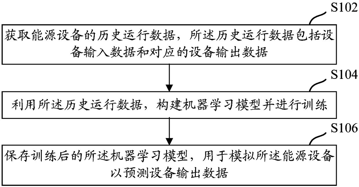
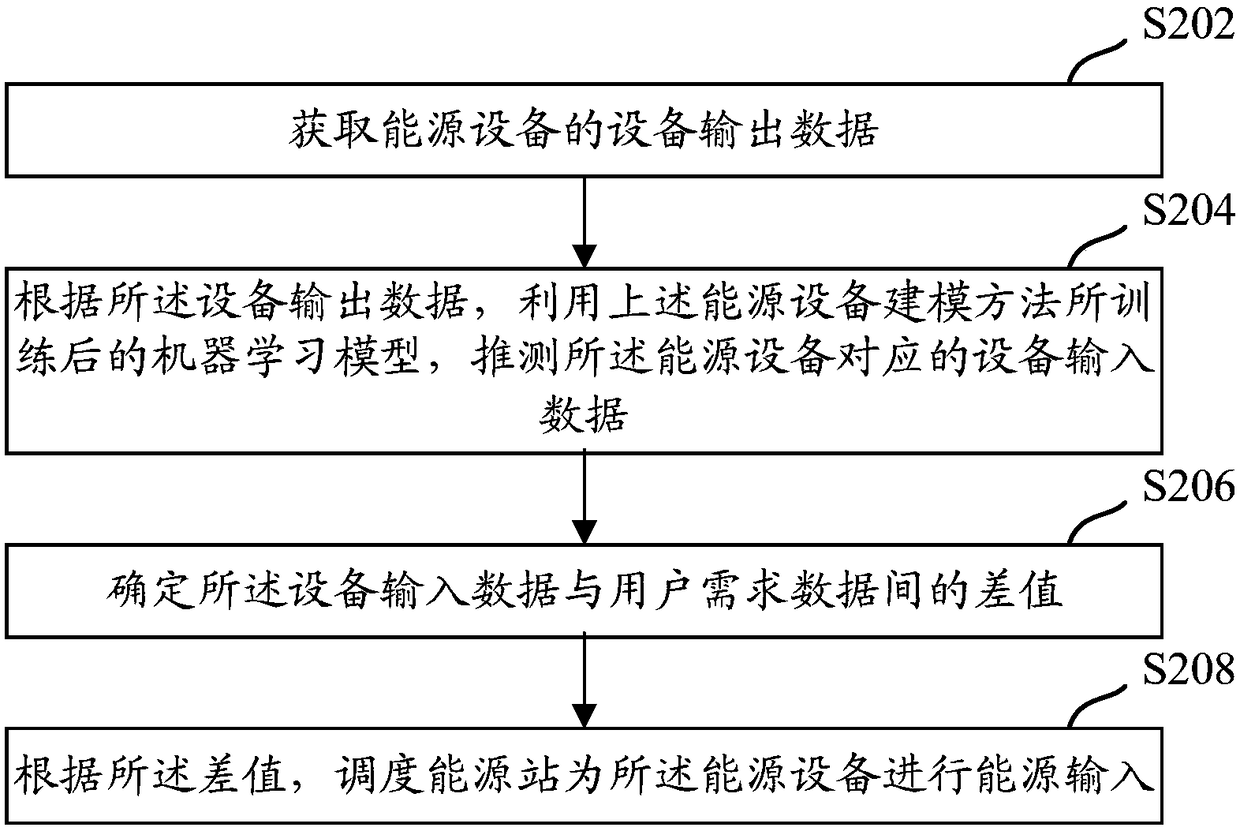
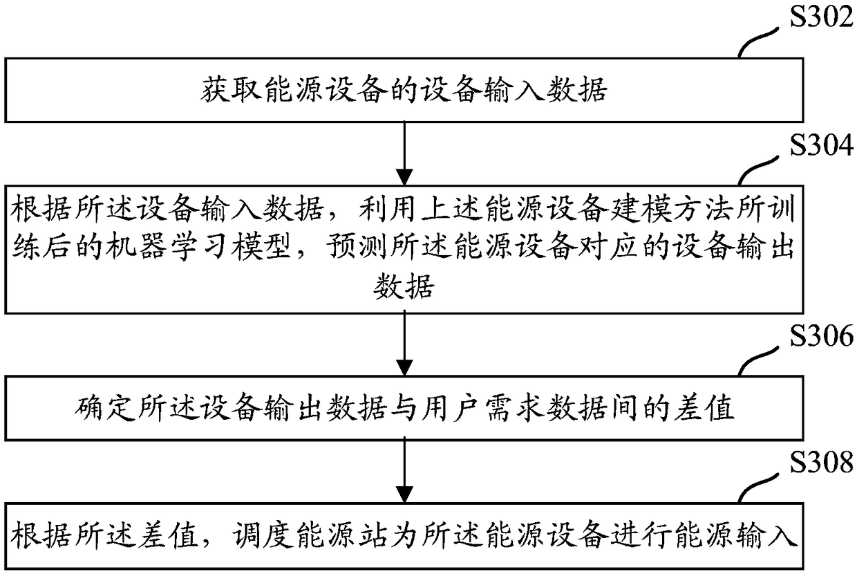
[0084] In practical applications, the purpose of modeling energy equipment is usually to understand the data relationship between the input and output of energy equipment, so as to facilitate the reasonable scheduling of energy stations to provide energy input for energy equipment. This application starts with the historical operation data of energy equi


PUM


Abstract

The invention discloses energy equipment modeling method, device and equipment and energy station scheduling method, device and equipment. According to the scheme, the energy equipment modeling methodcomprises the following steps of: obtaining historical operation data of energy equipment, wherein the historical operation data comprise equipment input data and corresponding equipment output data;constructing a machine learning model by utilizing the historical operation data and training; and storing the trained machine learning model which is used for simulating the energy equipment to predict the equipment output data and can also be used for dispatching an energy station to carry out energy input for the energy equipment according to the prediction result and user demand data. Therefore, the purpose of reasonably utilizing the energy is achieved while the user requirements can be met at the same time.

Description


Claims


Application Information

Patent Timeline
Owner ENNEW DIGITAL TECH CO LTD
Why Eureka
Try Eureka