Metal punching equipment

A technology of metal stamping and equipment, which is applied in the field of metal stamping, can solve problems such as the inability to effectively solve the problem of storage space, and achieve the effects of improving work coordination, reliability, and ease of use

Inactive Publication Date: 2018-10-12
骆婧怡 +4
View PDF5 Cites 0 Cited by
  • Summary
  • Abstract
  • Description
  • Claims
  • Application Information

AI Technical Summary

Problems solved by technology

[0002] Metal stamping is a manufacturing process that uses a metal stamping die or a series of metal stamping dies to form metal sheets into workpieces with three-dimensional dimensions. Metal stamping products are used in various indu

Method used


Image

  • Metal punching equipment
  • Metal punching equipment
  • Metal punching equipment

Examples


Embodiment Construction

[0020] All features disclosed in this specification, or steps in all methods or processes disclosed, may be combined in any manner, except for mutually exclusive features and / or steps.

[0021] Any feature disclosed in this specification (including any appended claims, abstract and drawings), unless expressly stated otherwise, may be replaced by alternative features which are equivalent or serve a similar purpose. That is, unless expressly stated otherwise, each feature is one example only of a series of equivalent or similar features.

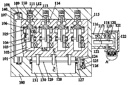
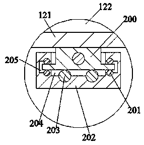
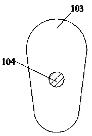
[0022] Such as Figure 1-4As shown, a metal stamping equipment of the present invention includes a frame body 100, and a first rotary cavity 108 with an opening facing the right is fixed inside the frame body 100, and the right end wall of the first rotary cavity 108 is communicated with a wall for Install the first loading cavity 115 of the metal stamping machine, and the upper end wall of the first loading cavity 115 is intercommunicated wit


PUM


Abstract

The invention discloses metal punching equipment. The metal punching equipment comprises a frame. A first rotation cavity with a rightward opening is fixedly formed in the frame. The interior of the right end wall of the first rotation cavity is provided with a first arranging cavity in a communication manner, wherein the first arranging cavity is used for installing a metal punching machine, anda plurality of first sliding cavities with downward openings are formed in the upper end wall of the first arranging cavity in a communication manner. The interior of the lower end wall of the first arranging cavity is provided with a second rotation cavity with an upward opening in a communication manner. The right side of the second rotation cavity is provided with a hole groove located in the frame. A first rotation pin shaft is rotationally arranged between the upper end wall and the lower end wall of the first rotation cavity. An opening and closing door is fixedly arranged on the outer surface of the first rotation pin shaft and penetrates the first arranging cavity. A plurality of third rotation cavities with upward openings are fixedly formed in the opening and closing door. The equipment is simple in structure and convenient to use; a dual locking manner is adopted in the equipment, the efficient storage and management function is achieved in the usage process, and the reliability of the metal punching machine is effectively improved.

Description


Claims


Application Information

Patent Timeline
Owner 骆婧怡
Why Eureka
Try Eureka