Portable new energy automobile stopping device

A new energy vehicle, portable technology, applied in portable braking system, vehicle parts, transportation and packaging, etc., can solve the problems of working personnel and surrounding items such as injury, improve work efficiency and service life, and increase handling strength , the effect of contact stability

Active Publication Date: 2018-10-12
湖北省奔翔汽配有限公司
View PDF9 Cites 4 Cited by
  • Summary
  • Abstract
  • Description
  • Claims
  • Application Information

AI Technical Summary

Benefits of technology

This patented technology describes an improved way to hold up a stopped automobile by adding extra supports that are connected together at specific angles. These supports help keep the bifold from getting stuck during stops while still providing stability against laterally sliping off. Additionally, this design allows for easier carrying around without having multiple tools like cranks or screwdrivers, making them less expensive than older designs. Overall, these technical features enhance the functionality and usability of current stopping devices such as those described earlier.

Problems solved by technology

This patented technology describes a problem where current vehicles have had issues with starting from batteries when they start running at high speeds due to their lacking fuel efficiency. These concerns include environmental hazards caused by exhaust gases produced during combustion processes, potential safety risks associated with flammability materials used inside cars, and excessive weight added to these structures themselves. To address this issue, research into developing better solutions involves creating smaller but stronger components called lampshades (LHS) instead of traditional metal plates like aluminium). However, LHC systems still require manual operation and take too much time before being able to fully utilized because they cannot detect if someone tries to damage them while driving around.

Method used


Image

  • Portable new energy automobile stopping device
  • Portable new energy automobile stopping device
  • Portable new energy automobile stopping device

Examples


Embodiment Construction

[0019] The following will clearly and completely describe the technical solutions in the embodiments of the present invention with reference to the accompanying drawings in the embodiments of the present invention. Obviously, the described embodiments are only some, not all, embodiments of the present invention. Based on the embodiments of the present invention, all other embodiments obtained by persons of ordinary skill in the art without making creative efforts belong to the protection scope of the present invention.

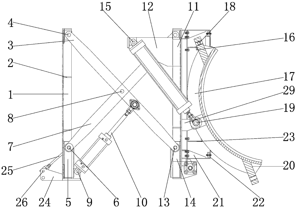
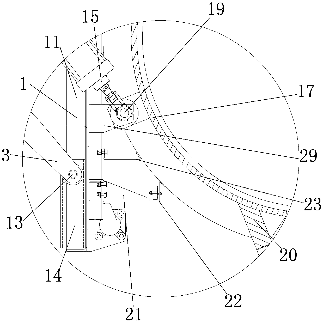
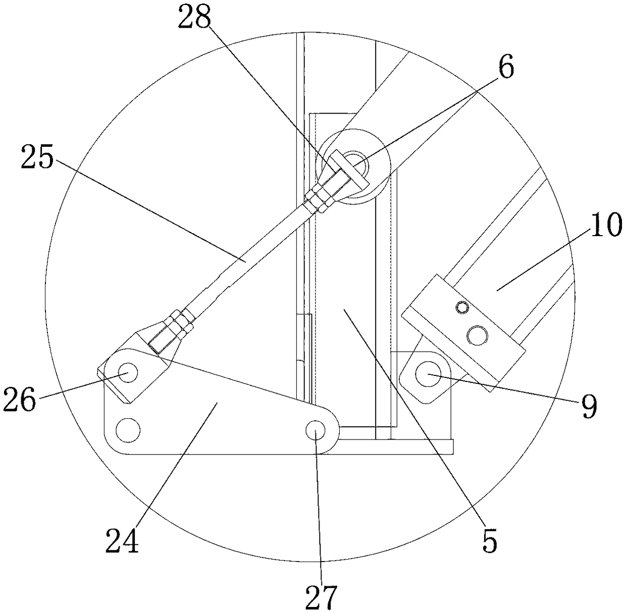
[0020] see Figure 1-3, the present invention provides a technical solution: a portable new energy vehicle car stopper, including a bottom plate 1 for installing and fixing the first pole 3 and the second pole 7, the inner wall of the bottom plate 1 is equipped with a connecting corner 2, It is used to reinforce the bottom plate 1, the outer wall of the connecting corner 2 is connected with the inner wall of the bottom plate 1, and the top of the outer wall of th


PUM


Abstract

The invention discloses a portable new energy automobile stopping device which comprises a bottom plate. A first supporting rod is arranged at the top end of the outer wall of the bottom plate, and afirst pin shaft is arranged on the inner wall of the first supporting rod. The inner wall of the first supporting rod is connected with the outer wall of the bottom plate through the first pin shaft,and a first sliding groove is formed in the inner wall of the bottom end of the bottom plate. The outer wall of the first sliding groove is connected with the inner wall of the bottom plate, and a second supporting rod is arranged on the inner wall of the first sliding groove. According to the portable new energy automobile stopping device, the first supporting rod, the second supporting rod, a third supporting rod and a fourth supporting rod are matched, and under the action of fixing corner braces, a top plate and the bottom plate are fixedly connected by the first supporting rod, the secondsupporting rod, the third supporting rod and the fourth supporting rod, so that the product quality of the portable new energy automobile stopping device is improved, the purchasing cost of a user issaved, the resource waste of the portable new energy automobile stopping device is avoided, and the stopping device is suitable for popularization and use.

Description


Claims


Application Information

Patent Timeline
Owner 湖北省奔翔汽配有限公司
Why Eureka
Try Eureka