Magnetic liquid sealing device adopting corrugated-pipe-assisted sealing

A magnetic liquid and sealing device technology, which is applied in the direction of engine sealing, engine components, mechanical equipment, etc., can solve the problems of limited installation accuracy, machining accuracy, reduced sealing reliability, friction and fatigue, and solve the damage of seals problem effect

Pending Publication Date: 2018-10-19
TSINGHUA UNIV
View PDF7 Cites 4 Cited by
  • Summary
  • Abstract
  • Description
  • Claims
  • Application Information

AI Technical Summary

Benefits of technology

This patented technology describes an improved design that allows for better control over pressure during operation without damaging sensitive components or causing leaks between parts. It achieves this through use of special materials called magnetoelastomer (ME) tubes with specific properties such as flexibility at different temperatures. These ME tube devices help protect these areas from being exposed to excessive force while still maintain their function properly.

Problems solved by technology

The technical issue addressed in this patented technology relates to improving the performance and lifespan of magneto fluid (MF) seals for use at high speeds without causing excessive wear or damage from these movements that can cause issues like abrasion and reduced efficiency.

Method used


Image

  • Magnetic liquid sealing device adopting corrugated-pipe-assisted sealing
  • Magnetic liquid sealing device adopting corrugated-pipe-assisted sealing

Examples


Embodiment Construction

[0024] Embodiments of the present invention are described in detail below, examples of which are shown in the drawings, wherein the same or similar reference numerals designate the same or similar elements or elements having the same or similar functions throughout. The embodiments described below by referring to the figures are exemplary and are intended to explain the present invention and should not be construed as limiting the present invention.

[0025] The following describes the magnetic liquid sealing device for auxiliary sealing of bellows according to the embodiments of the present invention with reference to the accompanying drawings.

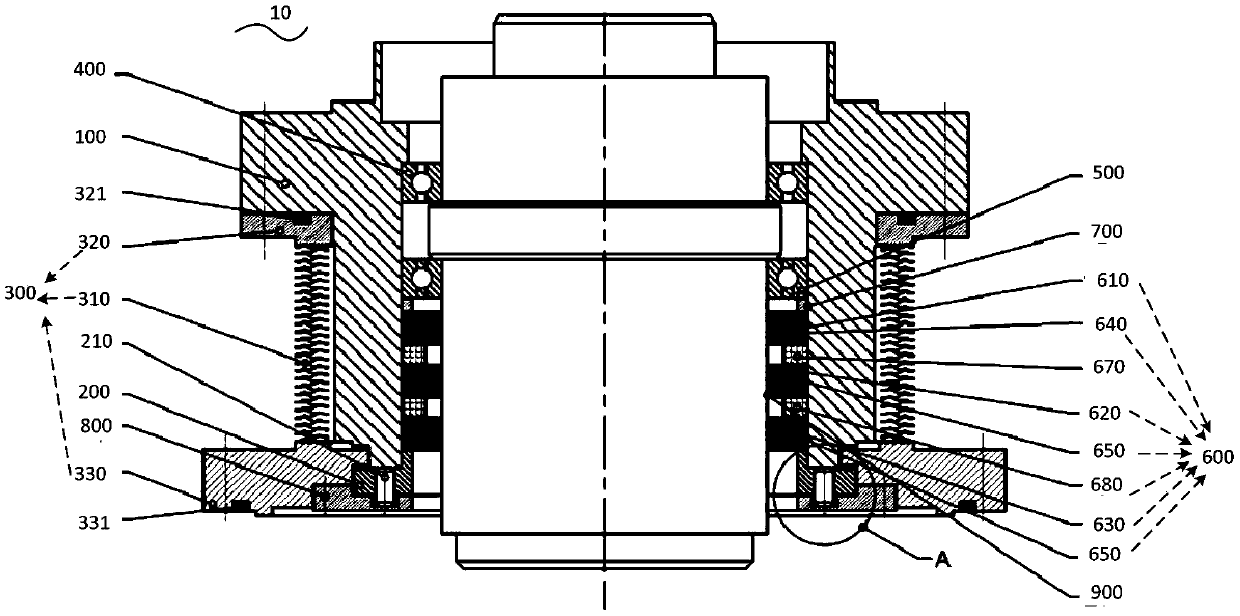
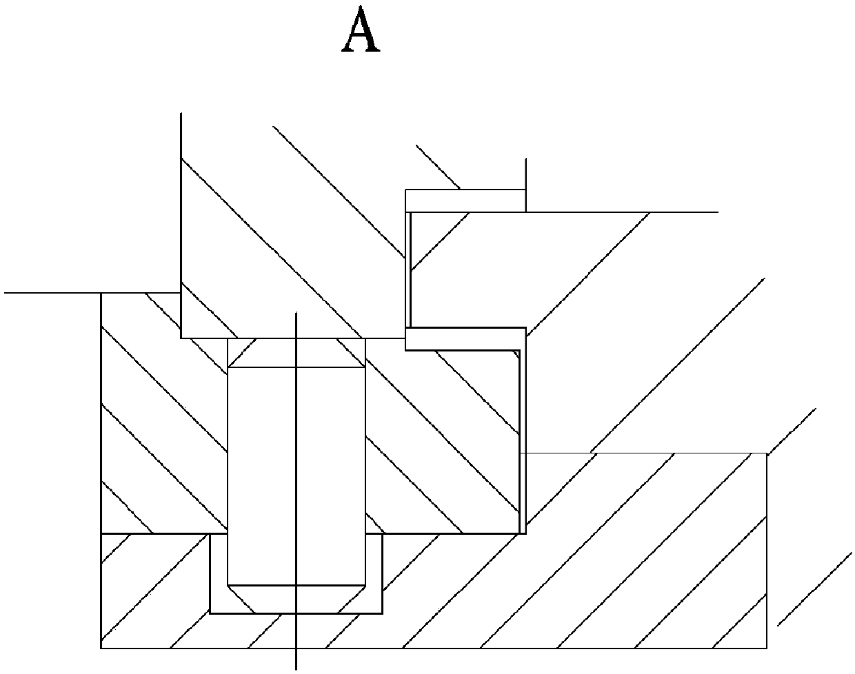
[0026] figure 1 It is a structural schematic diagram of a magnetic liquid sealing device for bellows auxiliary sealing according to an embodiment of the present invention.

[0027] Such as figure 1 As shown, the bellows assisted sealing magnetic liquid sealing device 10 includes: a seal housing 100 , a cylindrical pin sleeve 200 and a


PUM


Abstract

The invention discloses a magnetic liquid sealing device adopting corrugated-pipe-assisted sealing. The magnetic liquid sealing device comprises a sealing piece shell, a cylinder pin sleeve, a corrugated pipe, a corrugated pipe upper-end flange and a corrugated pipe lower-end flange. The cylinder pin sleeve is used for clearance control and positioning. The corrugated pipe is connected with the corrugated pipe upper-end flange and the corrugated pipe lower-end flange correspondingly in a welded manner. A sealing slot of the corrugated pipe upper-end flange is internally provided with a first sealing ring, and a sealing slot of the corrugated pipe lower-end flange is internally provided with a second sealing ring, so that a corrugated pipe assembly is formed. The corrugated pipe upper-end flange is in fit with the sealing piece shell, and preset gaps are reserved between the corrugated pipe lower-end flange and the cylinder pin sleeve and between the corrugated pipe lower-end flange andthe sealing piece shell. Corrugated-pipe-assisted sealing is adopted, a buffering role can be played through the elasticity of the corrugated pipe when a rotating shaft generates radial jump, and thus the problem of damages to a sealing piece caused by jump of the rotating shaft in a high-speed working condition is effectively solved.

Description


Claims


Application Information

Patent Timeline
Owner TSINGHUA UNIV
Why Eureka
Try Eureka