Speed measurement method applied to radar, speed measurement device and electronic equipment

A radar and speed measurement technology, applied in the field of radar, can solve the problems of radar speed measurement range limitation, spectrum overlap, radar target speed measurement confusion, etc., to meet application requirements and improve the effect of speed measurement range

Active Publication Date: 2018-10-19
WHST CO LTD
View PDF3 Cites 9 Cited by
  • Summary
  • Abstract
  • Description
  • Claims
  • Application Information

AI Technical Summary

Problems solved by technology

[0003] However, the radar system collects data signals through an analog-to-digital converter. Due to the limitation of the sampling rate of the analog-to-digital converter, when the sampling interval is too wide, it will cause sp

Method used


Image

  • Speed measurement method applied to radar, speed measurement device and electronic equipment
  • Speed measurement method applied to radar, speed measurement device and electronic equipment
  • Speed measurement method applied to radar, speed measurement device and electronic equipment

Examples


Embodiment Construction

[0045] In the following description, specific details such as specific system structures and technologies are presented for the purpose of illustration rather than limitation, so as to thoroughly understand the embodiments of the present invention. It will be apparent, however, to one skilled in the art that the invention may be practiced in other embodiments without these specific details. In other instances, detailed descriptions of well-known systems, devices, circuits, and methods are omitted so as not to obscure the description of the present invention with unnecessary detail.

[0046] In order to make the purpose, technical solution and advantages of the present invention clearer, specific embodiments will be described below in conjunction with the accompanying drawings.

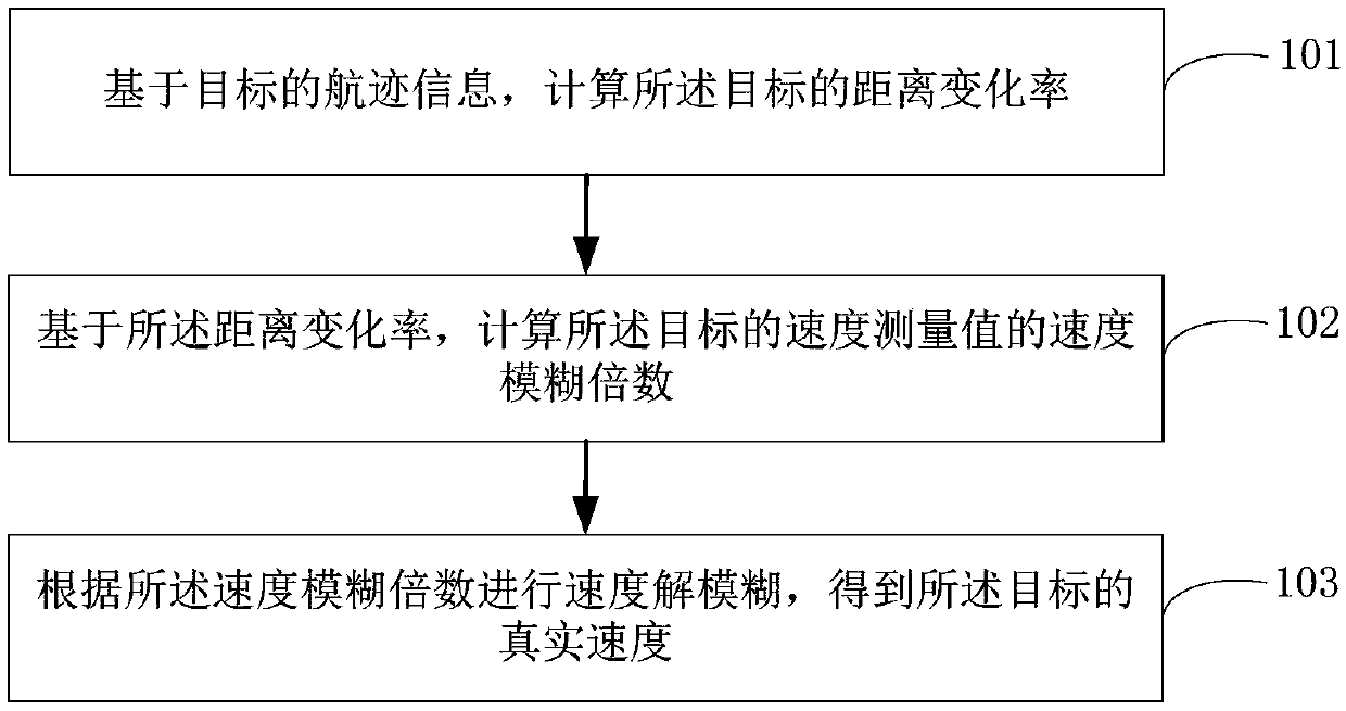
[0047] see figure 1 , which shows the implementation flow chart of the speed measurement method applied to radar provided by the embodiment of the present invention, and is described in detail as follows


PUM


Abstract

The invention is suitable for the radar technology field and provides a speed measurement method applied to a radar, a speed measurement device, electronic equipment and a computer readable storage medium. The speed measurement method comprises the following steps of based on the track information of a target, calculating the distance change rate of the target; based on the distance change rate, calculating the speed blur multiple of the speed measurement value of the target; and according to the speed blur multiple, carrying out speed deblur and acquiring the real speed of the target. In theinvention, the speed measurement range of the radar can be effectively increased and the application demand of a vehicle-borne radar is satisfied.

Description


Claims


Application Information

Patent Timeline
Owner WHST CO LTD
Why Eureka
Try Eureka