Magnetic field type single-anode-and-cathode electrophoretic coating equipment

A technology of cathodic electrophoresis and coating equipment, applied in electrolytic coatings, electrophoretic plating, coatings, etc., can solve the problems of poor electrophoretic deposition effect and poor uniformity of electrophoretic deposited coatings, and achieve improved effect, quality and convenience. , the effect of improving the density

Inactive Publication Date: 2018-11-02
ZHEJIANG HUIER COATING ENVIRONMENTAL PROTECTION EQUIP
View PDF13 Cites 3 Cited by
  • Summary
  • Abstract
  • Description
  • Claims
  • Application Information

AI Technical Summary

Benefits of technology

This patented technology improves the efficiency with which charges move through liquids when they hit surfaces like metal plates while depositing layers onto them. By applying electric fields that generate torque instead of just moving it around inside a tank containing liquid solvents, this process allows for more precise coatings without any issues caused from excess pressure differences between two sides. Additionally, there's no longer needs to use multiple electrical wires perpendicularly connected to each side of the device, making assembly easier than ever before. Overall, these technical improvements make better results compared to traditional methods.

Problems solved by technology

This patents describes various technical problem addressed in this patented technology relational text discussing how elec trokrography (electrode) techniques have limitations such as slow speed and complex operations due to factors like uneven thickening caused by charge transfer processes involving multiple charges. Additionally, some methods require expensive apparatus modifications and may result in reduced quality control compared to other methods.

Method used


Image

  • Magnetic field type single-anode-and-cathode electrophoretic coating equipment
  • Magnetic field type single-anode-and-cathode electrophoretic coating equipment
  • Magnetic field type single-anode-and-cathode electrophoretic coating equipment

Examples


Embodiment 1

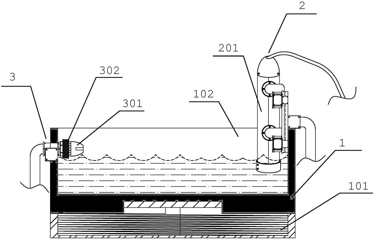
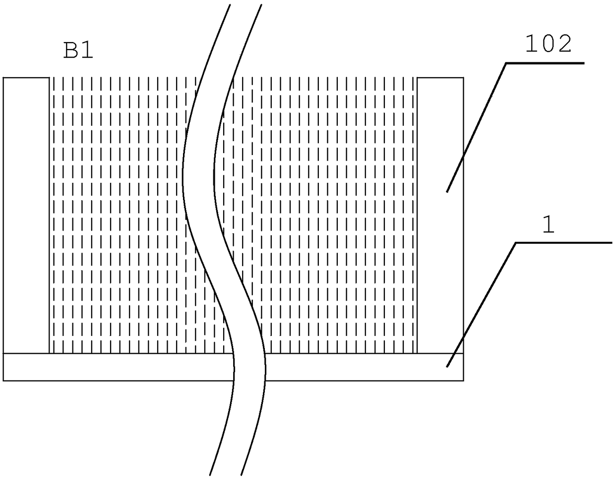
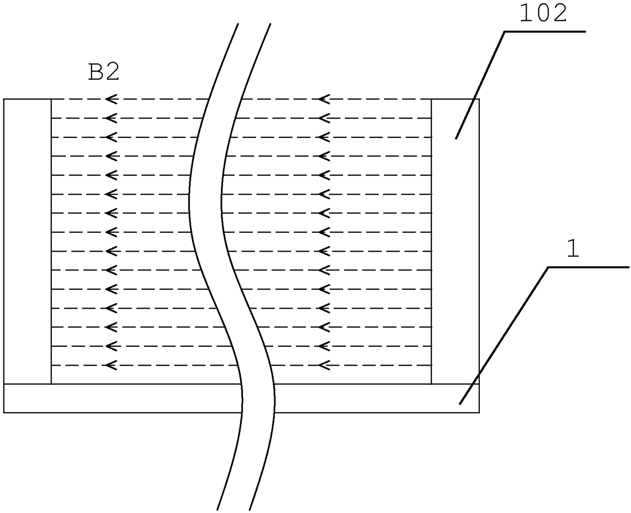
[0039] Such as figure 1 A magnetic field type single anode cathodic electrophoretic coating equipment shown includes an electrophoresis tank 1 and a cathode structure 3 and an anode structure 2 oppositely arranged in the electrophoresis tank 1, wherein the cathode structure 3 is provided with a steering mechanism 302, and the front end of the steering mechanism 302 is The clamping part 301 is fixedly connected, the anode structure 2 includes an anode column 201 for providing charged particles required for electrophoresis, the bottom of the electrophoresis tank 1 is provided with a first magnetic field generating mechanism 101, and the opposite side walls of the electrophoresis tank 1 are provided with second In the magnetic field generating mechanism 102, the two side walls of the second magnetic field generating mechanism 102 are interlaced with the two side walls of the cathode and anode. And ordinary cathodic electrophoretic coating equipment routinely equipped with auxiliary

Embodiment 2

[0052] Such as figure 1 A magnetic field type single anode cathodic electrophoretic coating equipment shown includes an electrophoresis tank 1 and a cathode structure 3 and an anode structure 2 oppositely arranged in the electrophoresis tank 1, wherein the cathode structure 3 is provided with a steering mechanism 302, and the front end of the steering mechanism 302 is The clamping part 301 is fixedly connected, the anode structure 2 includes an anode column 201 for providing charged particles required for electrophoresis, the bottom of the electrophoresis tank 1 is provided with a first magnetic field generating mechanism 101, and the opposite side walls of the electrophoresis tank 1 are provided with second In the magnetic field generating mechanism 102, the two side walls of the second magnetic field generating mechanism 102 are interlaced with the two side walls of the cathode and anode. And ordinary cathodic electrophoretic coating equipment routinely equipped with auxiliary


PUM


Abstract

The invention relates to the field of coating equipment, in particular to magnetic field type single-anode-and-cathode electrophoretic coating equipment which through lorentz force effect on charged particles through a magnetic field, and then the uniformity and compactness of the coating on the surface of a cathode to-be-machined material is greatly improved; the equipment comprises an electrophoresis tank, a cathode structure and an anode structure, wherein the cathode structure and the anode structure are oppositely arranged in the electrophoresis tank, a first magnetic field generating mechanism is arranged at the bottom of the electrophoresis tank, and second magnetic field generating mechanisms are arranged on the two opposite side walls of the electrophoresis tank.

Description


Claims


Application Information

Patent Timeline
Owner ZHEJIANG HUIER COATING ENVIRONMENTAL PROTECTION EQUIP
Why Eureka
Try Eureka