Forming machine for bimetallic strip

A bimetal sheet and forming machine technology, applied in metal processing equipment, feeding devices, positioning devices, etc., can solve the problems of small damage to the surface of the workpiece, thinning of the arc end of the workpiece, and short service life of the mold, etc., to achieve Improve production efficiency, avoid stretching deformation, stable and reliable operation

Pending Publication Date: 2018-11-06
中国振华电子集团宇光电工有限公司(国营第七七一厂)
View PDF0 Cites 1 Cited by
  • Summary
  • Abstract
  • Description
  • Claims
  • Application Information

AI Technical Summary

Problems solved by technology

However, there are many problems in the molding process of these two methods.
Rigid die forming method as attached Figure 12 As shown, there are the following defects: 1. In the early stage of feeding, it is easy to cause damage at point a on the surface of the lower die surface of the workpiece; 2. In the early stage of feeding, affected by the hardness of the workpiece, it is easy to cause a sudden change at the bending point b on the top of the workpiece, although it can pass through the mold Bottom correction, but it is easy to cause metal damage at the mutation point of the workpiece; 3. The stroke of the mold is not easy to control, and the over-stroke will easily cause the arc end of the workpiece to be over-extruded and thinned, caus

Method used


Image

  • Forming machine for bimetallic strip
  • Forming machine for bimetallic strip
  • Forming machine for bimetallic strip

Examples


Embodiment Construction

[0028] The present invention will be further described below in conjunction with the drawings and embodiments, but it is not a basis for limiting the present invention.

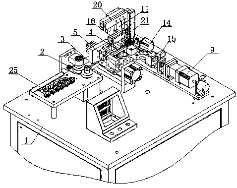
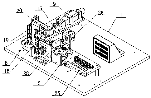
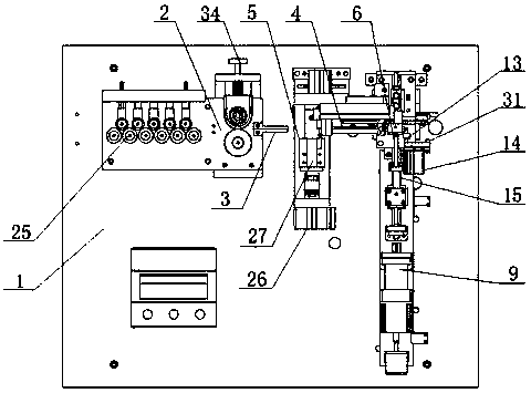
[0029] The embodiment of the present invention: a bimetal sheet forming machine, as attached Figure 1-10 As shown, the fuselage 1 is included. The top left of the fuselage 1 is provided with a feeding mechanism 2, the right side of the feeding mechanism 2 is provided with a first feeding guide 3, and the right of the first feeding guide 3 is provided with a second feeding guide 4, 2 Two feeding rails are on the same horizontal line. A cutting mechanism 5 is provided between the two feeding rails. The right side of the second feeding rail 4 is provided with a horizontal and vertical forming rail 6 which is equipped with a forming mold structure and a forming mold. The structure includes an inner mold 7, a positioning ejector 8 is provided behind the inner mold 7, a gap is left between the two, an inner mold pusher


PUM


Abstract

The invention discloses a forming machine for a bimetallic strip. A forming mold structure is arranged in a forming guide rail; the forming mold structure comprises an inner mold, a positioning jacking rod is arranged behind the inner mold, and a gap is reserved between the inner mold and the positioning jacking rod; an inner mold pushing rod is arranged in front of the inner mold, a forming stepping motor is arranged in front of the inner mold pushing rod, the positioning jacking rod is connected with a material pressing air cylinder, and the material pressing air cylinder is arranged on theposition, on the upper portion of a machine body, of a rack; two sets of lifting positioning clamps are arranged on the position, at the intersection of the extending line of a second feeding guide rail and a forming guide rail, of the left side and the right side of the forming guide rail correspondingly; a gap is formed between each set of lifting positioning clamps; a head end bending forming mold is arranged on the right side of the lifting positioning clamp on the right side and connected with a shaping air cylinder; and two movable idler wheels are arranged on the position, behind the lifting positioning clamps, of the left side and the right side of the forming guide rail correspondingly. In the process of using the forming machine to bend a material belt, damage to the surface of the material belt and the bent position of the material belt is avoided, the stroke of the mold is easy to control, and the service life is long.

Description


Claims


Application Information

Patent Timeline
Owner 中国振华电子集团宇光电工有限公司(国营第七七一厂)
Why Eureka
Try Eureka