Aircraft landing gear lifting device and lifting method thereof

A technology of aircraft landing gear and lifting device, which is applied in the direction of lifting device, aircraft maintenance, lifting gear, etc., can solve the problems of inability to move the landing gear and low efficiency of lifting equipment, and achieve high market promotion value, convenient movement or The effect of changing tires and improving maintenance efficiency

Active Publication Date: 2020-01-21
HEFEI YIHANG MACHINERY TECH CO LTD
View PDF6 Cites 0 Cited by
  • Summary
  • Abstract
  • Description
  • Claims
  • Application Information

AI Technical Summary

Benefits of technology

This patented technology allows for easy removal and installation of an elevated slot plate on top of existing runways during flight operations without having to stop work altogether. By matching this lift system with its own wheel hubs, it can move upwardly along rails that support the weight of the wheels attached to them while also allowing these components to be easily replaced when needed. Overall, this innovation enhances the performance and durability of the entire landing gears used by pilots flying from different locations around the world.

Problems solved by technology

This patented technical problem addressed by this patents relates to improving upon current methods of supporting and moving aircraft during take-off and flight phases due to their complexity and discomforts associated with being supported at one location while also allowing them to work safely alongside other parts of the vehicle's body.

Method used


Image

  • Aircraft landing gear lifting device and lifting method thereof
  • Aircraft landing gear lifting device and lifting method thereof
  • Aircraft landing gear lifting device and lifting method thereof

Examples


Embodiment Construction

[0030] The following will clearly and completely describe the technical solutions in the embodiments of the present invention with reference to the accompanying drawings in the embodiments of the present invention. Obviously, the described embodiments are only some, not all, embodiments of the present invention. Based on the embodiments of the present invention, all other embodiments obtained by persons of ordinary skill in the art without creative efforts fall within the protection scope of the present invention.

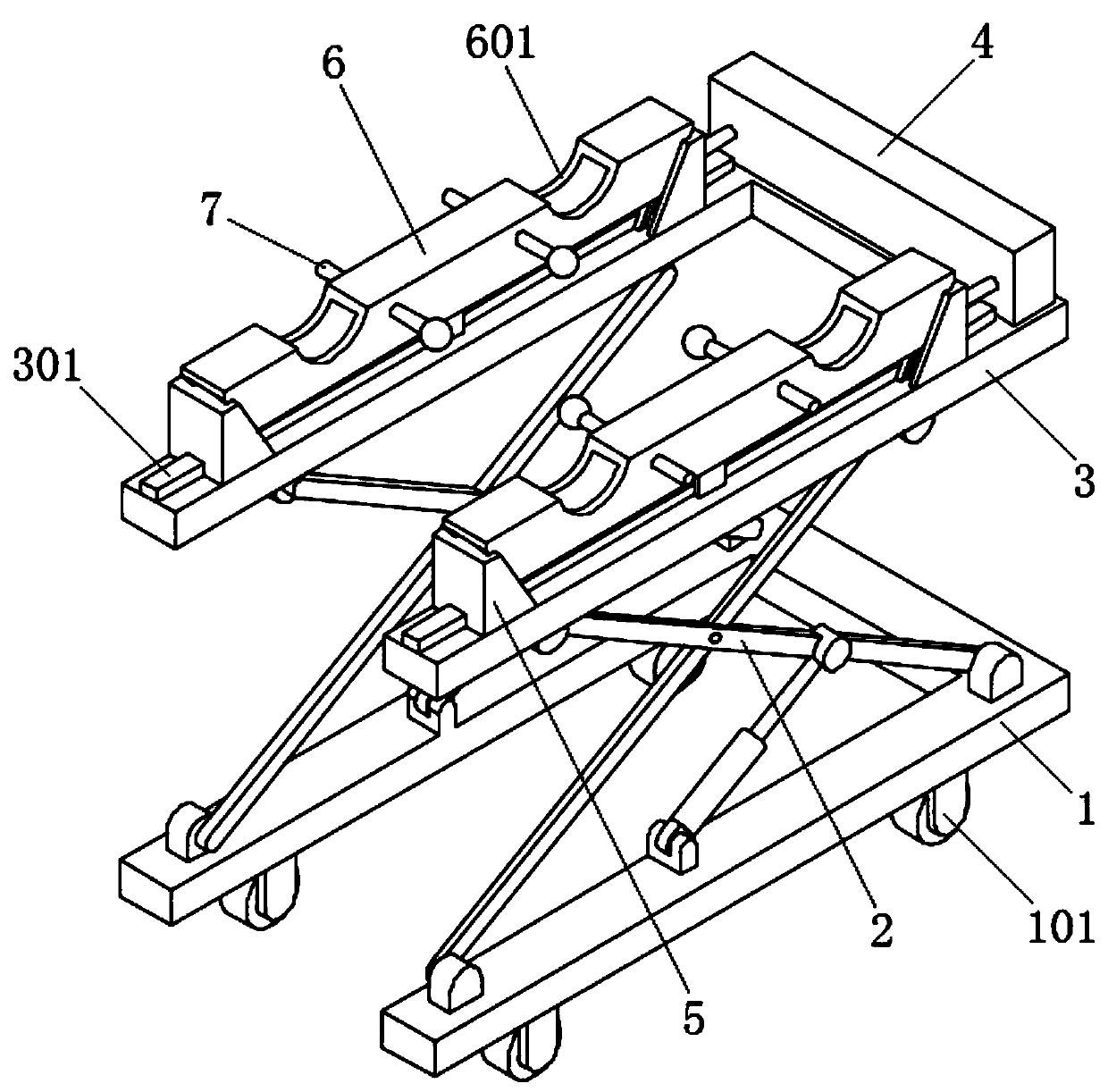
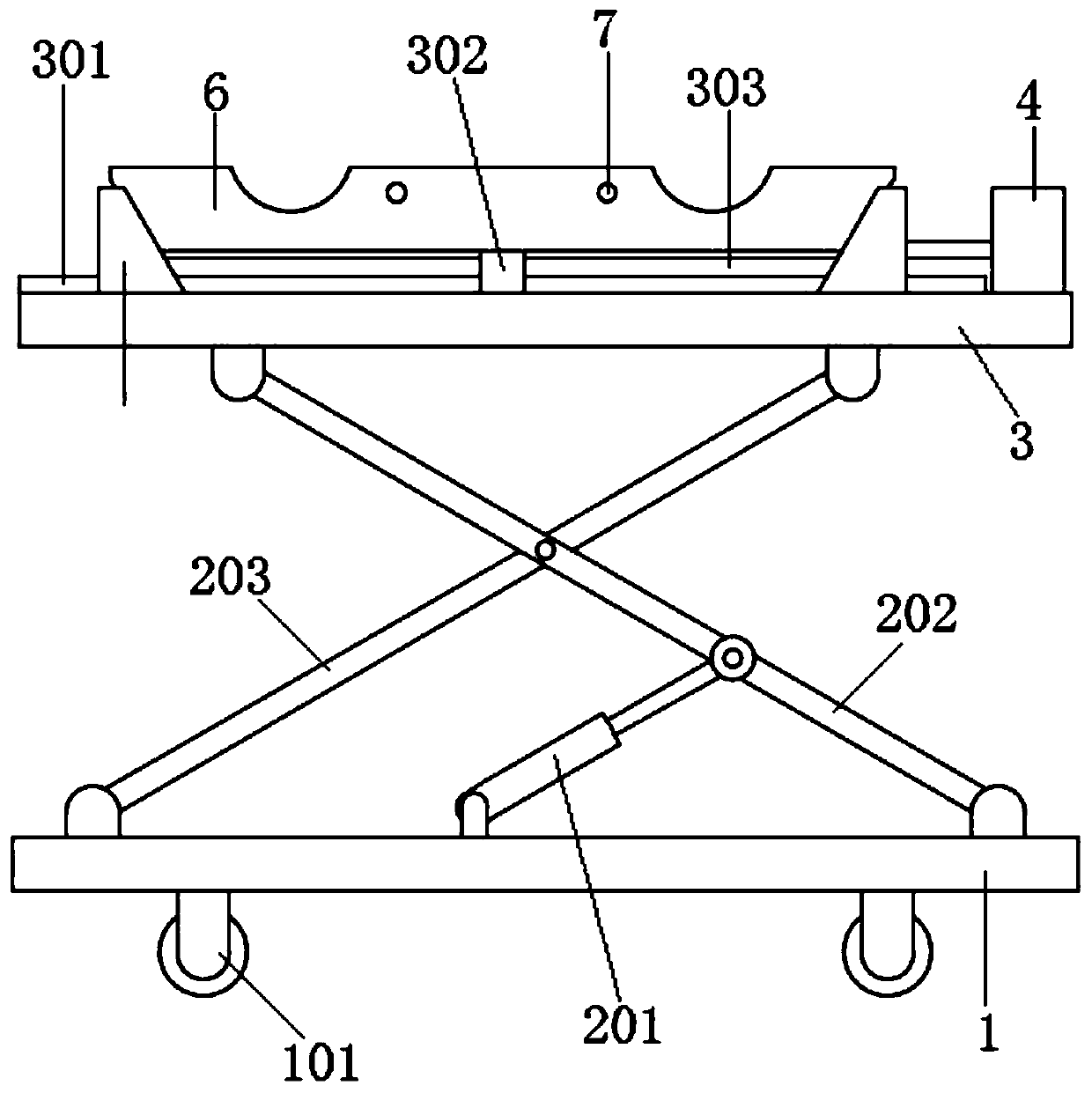
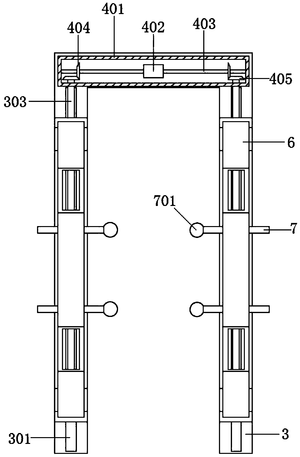
[0031] see Figure 1-5 As shown, the present invention is an aircraft landing gear lifting device, which includes a base plate 1 with two sets of road wheels 101 arranged side by side on the lower surface; the base plate 1 is in a U-shaped structure, which improves the overall compactness and aesthetics of the device; the base plate 1 The upper surface is equipped with a U-shaped plate 3 through a lifting mechanism 2; a power mechanism 4 is installed on the upper surf


PUM


Abstract

The invention discloses an aircraft landing gear lifting device and a lifting method thereof, and relates to the technical field of lifting equipment. The invention comprises a bottom plate; a U-shaped plate is installed on the upper surface of the bottom plate through a lifting mechanism; a power mechanism is installed on the U-shaped plate; guide rails are fixed on the upper surfaces of two opposite arms of the U-shaped plate; Screw rod; one end of the two-way screw rod is connected with the output shaft of the power mechanism; sliders are arranged on both sides of the fixed block; a lifting groove plate is arranged between the two sliders; The upper surface of the lifting groove plate is provided with card slots side by side. The invention moves the lifting groove plate to the designated position through the lifting mechanism, and uses the power mechanism to match the lifting groove plate with the axle of the landing gear, which facilitates the movement of the landing gear of the aircraft or the replacement of tires, and has high market promotion value.

Description


Claims


Application Information

Patent Timeline
Owner HEFEI YIHANG MACHINERY TECH CO LTD
Why Eureka
Try Eureka