Rotating platform with separated rotating discs

A rotating platform, separate technology, applied in the direction of machine/stand, supporting machine, mechanical equipment, etc., can solve the problems of insufficient applicability and inability to disassemble, and achieve the effect of simple structure, high practicability, and convenient operation and use

Inactive Publication Date: 2018-11-13
SUZHOU SHELE INTELLIGENT TECH CO LTD
View PDF18 Cites 0 Cited by
  • Summary
  • Abstract
  • Description
  • Claims
  • Application Information

AI Technical Summary

Problems solved by technology

At present, the rotating disks of most rotating platforms are fixed, so they cannot be disas

Method used


Image

  • Rotating platform with separated rotating discs

Examples


Example Embodiment

[0014] The technical solutions in the embodiments of the present invention will be described clearly and completely below. Obviously, the described embodiments are only a part of the embodiments of the present invention, rather than all the embodiments. Based on the embodiments of the present invention, all other embodiments obtained by those of ordinary skill in the art without creative work shall fall within the protection scope of the present invention:

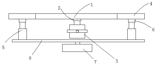
[0015] Such as figure 1 A rotating platform with a separate turntable is shown, including a central platform mechanism and an edge platform mechanism. The central platform mechanism includes a central turntable 1, a central transmission rod 2 and a central drive motor 3. The central transmission rod is vertically connected to At the lower middle position of the middle turntable, the middle drive motor is connected to the lower end of the middle transmission rod. The edge platform mechanism includes an annular turntable 4, a lift


PUM


Abstract

The invention discloses a rotating platform with separated rotating discs. The rotating platform comprises a central platform mechanism and an edge platform mechanism. The central platform mechanism comprises the central rotating disc, a central transmission rod and a central driving motor. The central transmission rod is perpendicularly connected to the middle of the lower portion of the centralrotating disc. The central driving motor is in transmission connection with the lower end of the central transmission rod. The edge platform mechanism comprises the annular rotating disc, a lifting mechanism, a plurality of outer side supporting rods and an outer side driving motor. The multiple outer side supporting rods are fixed to the lower side of the annular rotating disc in a supporting mode. The lower ends of the outer side supporting rods are connected with lifting mechanisms. A rotating seat is arranged on the lower portions of the lifting mechanisms. The outer side driving motor drives the rotating seat to freely rotate. The rotating platform with the separated rotating discs is simple in structure and convenient to operate and use, free combination and separation of the rotating discs of the platform can be effectively realized, the rotating discs can freely rotate relatively, and practicability is high.

Description


Claims


Application Information

Patent Timeline
Owner SUZHOU SHELE INTELLIGENT TECH CO LTD
Why Eureka
Try Eureka