Interface configuration method and system

A technology of interface configuration and DC circuit breaker, applied in the direction of circuit devices, electrical components, etc., can solve the problems of inapplicable flexible DC control protection system and DC circuit breaker interface, DC circuit breaker, etc., to facilitate link fault inspection, The effect of clear interface

Active Publication Date: 2018-11-13
NR ELECTRIC CO LTD +3
View PDF6 Cites 2 Cited by
  • Summary
  • Abstract
  • Description
  • Claims
  • Application Information

AI Technical Summary

Benefits of technology

This technology allows for flexibility in controlling and protective devices used with an alternating current (AC) electricity distribution network. It eliminates the need for multiple separate components like relays or switches, making it more efficient than traditional methods. Additionally, this method ensures quick response times while still providing reliable connections between different parts of the electrical grid.

Problems solved by technology

This patented technical solution describes an issue where traditional methods used for switching from AC sources to direct currents (DC) require long periods before they work properly or fail over again if there were any issues during their use.

Method used


Image

  • Interface configuration method and system
  • Interface configuration method and system
  • Interface configuration method and system

Examples


Embodiment Construction

[0026] The technical solutions of the present invention will be described in detail below in conjunction with the accompanying drawings.

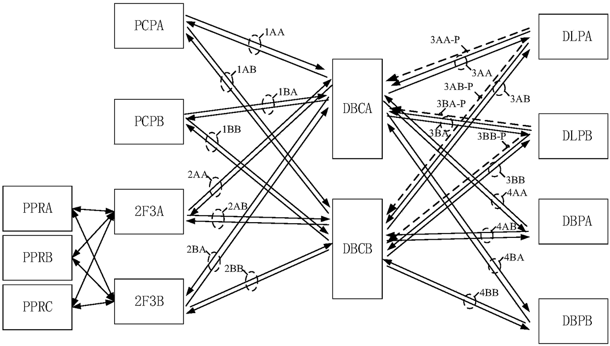
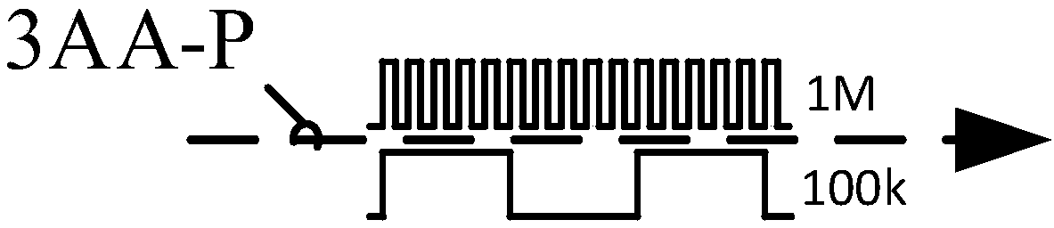
[0027] The present invention provides an interface configuration method for realizing the interface between a flexible DC control and protection system and a DC circuit breaker control system. The flexible DC control and protection system includes pole control, pole protection, DC busbar protection and DC line protection equipment. The pole control, pole protection, DC busbar protection or DC line protection equipment described above is connected with the DC circuit breaker control equipment to be operated using a standard protocol bidirectional interface communication link point-to-point connection; the control protection equipment of the flexible DC control protection system When rapid exit tripping is required, a one-way high-frequency communication link is also configured with the DC circuit breaker control device to be operated, and the DC


PUM


Abstract

The invention discloses an interface configuration method. Bidirectional interface communication link point-to-point connections adopting standard protocols are configured between pole control, pole protection, direct-current busbar protection or direct-current line protection devices and a direct-current circuit breaker control device to be operated. According to the method, since the bidirectional point-to-point links are configured between the control and protection devices in a flexible direct-current system and the direct-current circuit breaker to be operated, the influence of the switching out of a single control and protection device on the operation of the direct-current circuit breaker by other operating devices can be avoided; a high-frequency fast tripping link is additionallyconfigured for a line protection device which needs quick switching out, so that the line protection device can reliably trip the direct-current circuit breaker at a high speed. The invention also discloses an interface configuration system.

Description


Claims


Application Information

Patent Timeline
Owner NR ELECTRIC CO LTD
Why Eureka
Try Eureka