Double-glass assembly and battery piece arrangement structure

A double-glass module and cell technology, applied in circuits, photovoltaic power generation, electrical components, etc., can solve the problems of large changes in light intensity, affecting the growth of crops, wasting glass, etc., to improve light transmittance, improve light uniformity, The effect of increasing production

Pending Publication Date: 2018-11-23
HAINAN NORMAL UNIV
View PDF0 Cites 1 Cited by
  • Summary
  • Abstract
  • Description
  • Claims
  • Application Information

AI Technical Summary

Benefits of technology

This patented technology allows for efficient utilization of sunlight during photosynthesis by placing multiple layers of different types of plates onto surfaces that reflect or transmit certain wavelengths of visible rays back into their own energy source called photoelectric cells (PEC). These PEC devices convert this invisible radiation from sunrays directly into electric current without relying solely upon fossil fuels like oil. By doing these processes with less expensive equipment than traditional methods, it provides more affordable options compared to older ways such as burning coal at home.

Problems solved by technology

This patented technical solution described for improving the efficiency of capturing sunlight during photosynthesis involves arranging two types of cells: an upper layer made up mostly of silicon dioxide (SiO2) or another material called siliarylium into a special way designed specifically for efficient transmission of visible rays from certain areas around the plant being cultivated. By doing this, there will be fewer holes left where plants may grow but still receive enough light to promote their healthiness. Additionally, these arrangements help prevent damage caused by changes in brightness levels near those points where they were captured, resulting in improved overall production rates without wasting any valuable space needed.

Method used


Image

  • Double-glass assembly and battery piece arrangement structure
  • Double-glass assembly and battery piece arrangement structure

Examples


specific Embodiment approach 1

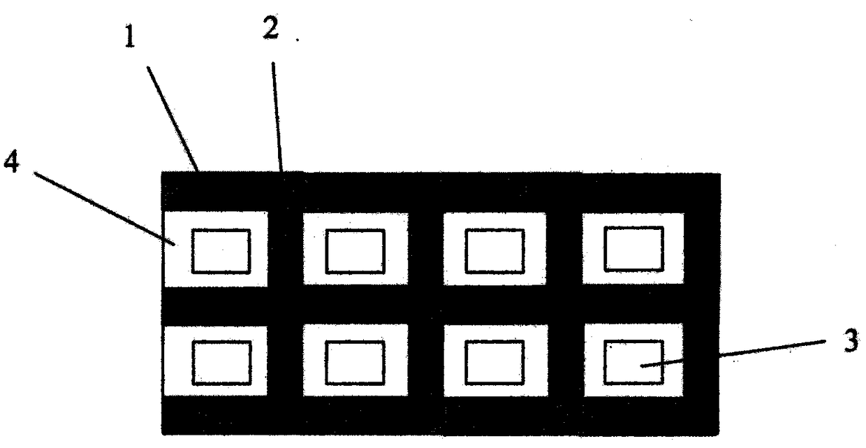
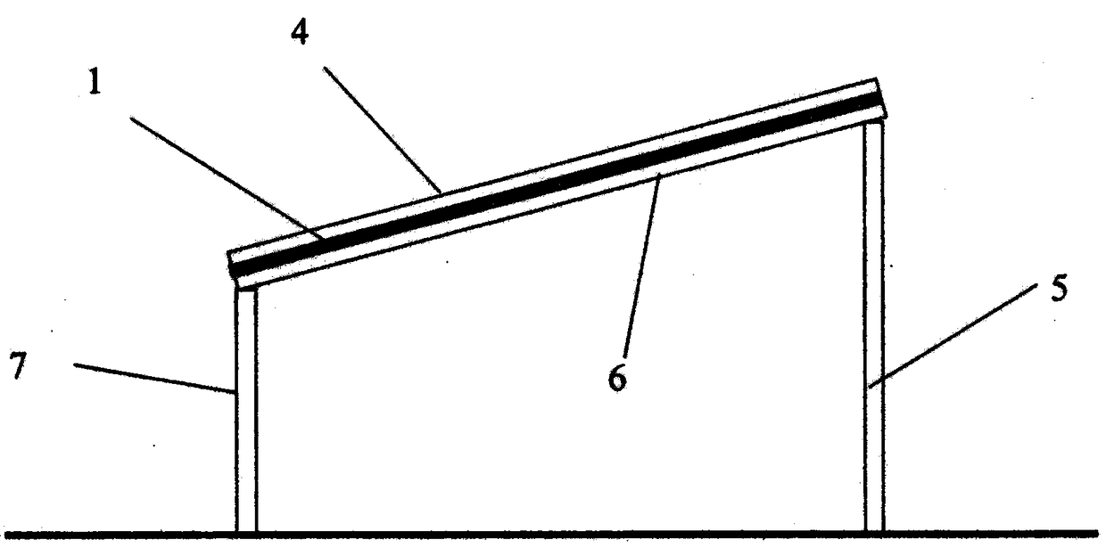
[0012] As in the accompanying drawings figure 1 , figure 2 As shown, a double-glass module and its cell installation structure include a first photovoltaic cell 1, a second photovoltaic cell 2, a transparent upper cover 4, a transparent back plate 6, a first pillar 5, and a second pillar 7. The first photovoltaic cells 1 and the second photovoltaic cells 2 are arranged between the transparent upper cover plate 4 and the transparent back plate 6. The first photovoltaic cells 1 are arranged in several rows, and the distance between adjacent rows is the same. Each row Adjacent first photovoltaic cells 1 are adjacent to each other, and the distance between adjacent rows is equal to the size of the long side of the second photovoltaic cells 2. The second photovoltaic cells 2 are arranged in several rows at equal intervals and placed on the first photovoltaic cells 1. Between several rows arranged, the long side of the second photovoltaic cells 2 is perpendicular to several rows of c

specific Embodiment approach 2

[0018] 1. As shown in the accompanying drawings of the manual figure 1 , figure 2 As shown, the arrangement structure of the double-glass module and its cells also includes several holes 3, and several first photovoltaic cells 1 of the same size and several second photovoltaic cells 2 of the same size constitute several size For the same square transparent areas, there is a hole 3 in the middle of each square transparent area.

[0019] According to the requirements of the above-mentioned arrangement method of photovoltaic cells, photovoltaic cell manufacturers can manufacture the double-glass modules, and the manufacturing technology of double-glass modules is currently very mature.

[0020] Double-glass components are generally installed at a certain inclination angle to the ground, and the specific inclination angle is calculated and determined according to the local geographical location. There are many calculation methods in this area and they are very mature. It is a well-


PUM


Abstract

Disclosed is a double-glass assembly and battery piece arrangement structure. According to the arrangement structure, battery pieces in the double-glass assembly are required to be uniformly arrangedat equal intervals, so that a hole-shaped or close-hole-shaped transparent area is formed among the battery pieces, and the double-glass assembly is arranged at a certain height from the ground; and ahole is formed in the middle of each hole-shaped or close-hole-shaped transparent area. According to the method, uniform illumination can be realized, the light transmittance is improved, and materials such as glass and the like are saved, so that a better growing environment is provided for crops, and the arrangement structure can be widely applied to photovoltaic greenhouses, lawns and farmlands; a bottleneck which restricts the popularization and use of solar photovoltaic power generation is broken through; and the power generation cost of solar photovoltaic power generation is remarkablyreduced, and the economic benefits are improved.

Description


Claims


Application Information

Patent Timeline
Owner HAINAN NORMAL UNIV
Why Eureka
Try Eureka