Broadband out-phase power combiner

A power combiner and power amplifier technology, which is applied in the field of radio frequency communication, can solve the problems of not meeting the requirements of the communication system and narrow bandwidth, and achieve the effects of reducing the influence of parasitic parameters, expanding bandwidth, and increasing performance

Inactive Publication Date: 2018-11-23
HANGZHOU DIANZI UNIV
View PDF10 Cites 2 Cited by
  • Summary
  • Abstract
  • Description
  • Claims
  • Application Information

AI Technical Summary

Problems solved by technology

However, the applicant found in the research that in fact the traditional Chireix power synthesizer is designed according to a single frequency point, so the bandwidth of this synthesizer is relatively narrow, which has a greater impact on the amplification of communication signals with a certain bandwidth, otherwise it will affect the The linearity, output power and efficiency of the entire out-of-phase power amplificatio

Method used


Image

  • Broadband out-phase power combiner
  • Broadband out-phase power combiner
  • Broadband out-phase power combiner

Examples


Embodiment 1

[0036] Embodiment one, such as image 3 As shown, the Chireix power combiner includes two straight microstrip lines TL1 and TL2 with the same structure, the branch where the straight microstrip line TL1 is located is the upper branch, and the branch where the straight microstrip line TL2 is located is the lower branch; the bandwidth expansion circuit Two straight microstrip lines TL3 and TL4 are connected in series. The output impedance of the upper branch is Z 1 , the output impedance of the lower branch is Z 2 , the total output impedance is Z 3 , 2Z 3 = Z 1 = Z 2 .

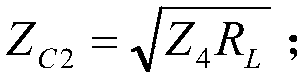
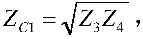
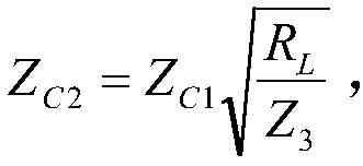
[0037] The microstrip line TL4 is a λ / 4 microstrip line, namely where Z C2 is the characteristic impedance of the microstrip line TL4, R L For the load, the load impedance is 50 ohms. The microstrip line TL3 is a λ / 4 microstrip line, similarly Z C1 is the characteristic impedance of the microstrip line TL3; but The microstrip line TL1 is a λ / 4 microstrip line, then

[0038]It is obtained


PUM


Abstract

The invention relates to a broadband out-phase power combiner. The broadband out-phase power combiner comprises a switch power amplifier, a Chireix power combiner and a bandwidth extension circuit; the Chireix power combiner is connected between the switch power amplifier and a load in series; and the bandwidth extension circuit is connected between the Chireix power combiner and the load in series. Two out-phase broadband modulation signals are input to the circuit simultaneously, the positive signal is input to the upper branch circuit, the negative signal is input to the lower branch circuit, the two signals are integrated by the Chireix power combiner and then output by the bandwidth extension circuit, and the output signal is absorbed by the load. According to broadband out-phase power combiner, the quality factors of a matching circuit are reduced by adopting the bandwidth extension circuit by means of step impedance matching, a big influence is achieved on combination of communication signals such as the WCDMA signal and the LTE signal which have the certain bandwidth, and then the linearity, the output power and the efficiency in the overall passband are influenced.

Description


Claims


Application Information

Patent Timeline
Owner HANGZHOU DIANZI UNIV
Why Eureka
Try Eureka