Ultra-Wideband Antenna

a wideband antenna and antenna earthing technology, applied in the structural form of resonant antennas, antenna earthings, radiating elements, etc., can solve the problem of miniaturization trend of portable electronic devices, achieve excellent and improvable performance, reduce manufacturing costs, and simple and compact structur

Inactive Publication Date: 2011-01-27
CHENG UEI PRECISION IND CO LTD
View PDF4 Cites 1 Cited by
  • Summary
  • Abstract
  • Description
  • Claims
  • Application Information

AI Technical Summary

Benefits of technology

The present technology describes an improved design for wireless communication devices that can operate at different frequencies with better performance than existing designs. This means they are smaller but still have good signal quality even when used over longer periods of time without being replaced or repaired more frequently.

Problems solved by technology

The technical problem addressed in this patented text relates to finding ways to make smaller UWB antennas while still being able to cover different frequencies within one band without making them bigger or requiring complicated structures like traditional designs.

Method used


Image

  • Ultra-Wideband Antenna
  • Ultra-Wideband Antenna
  • Ultra-Wideband Antenna

Examples


Embodiment Construction

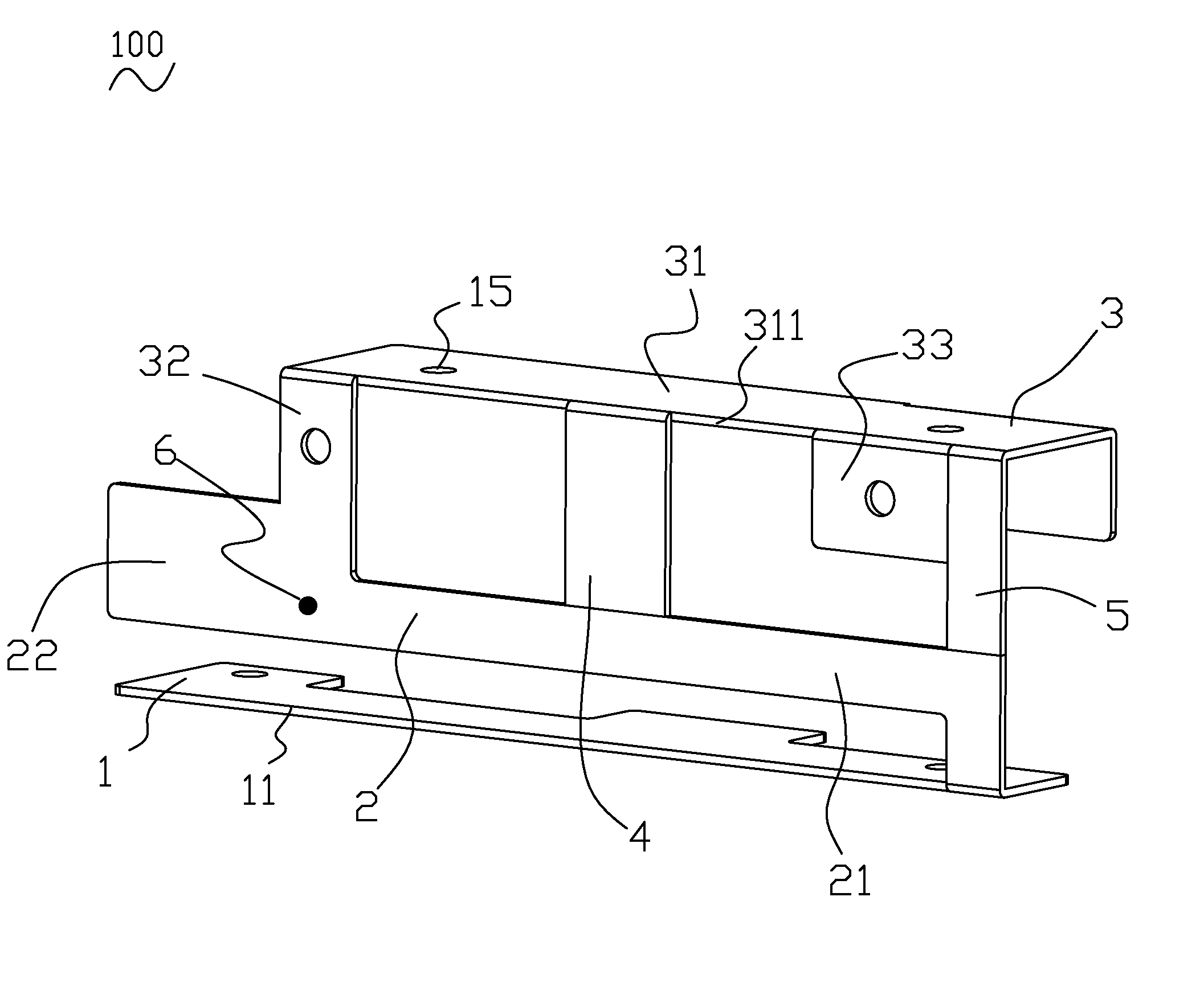
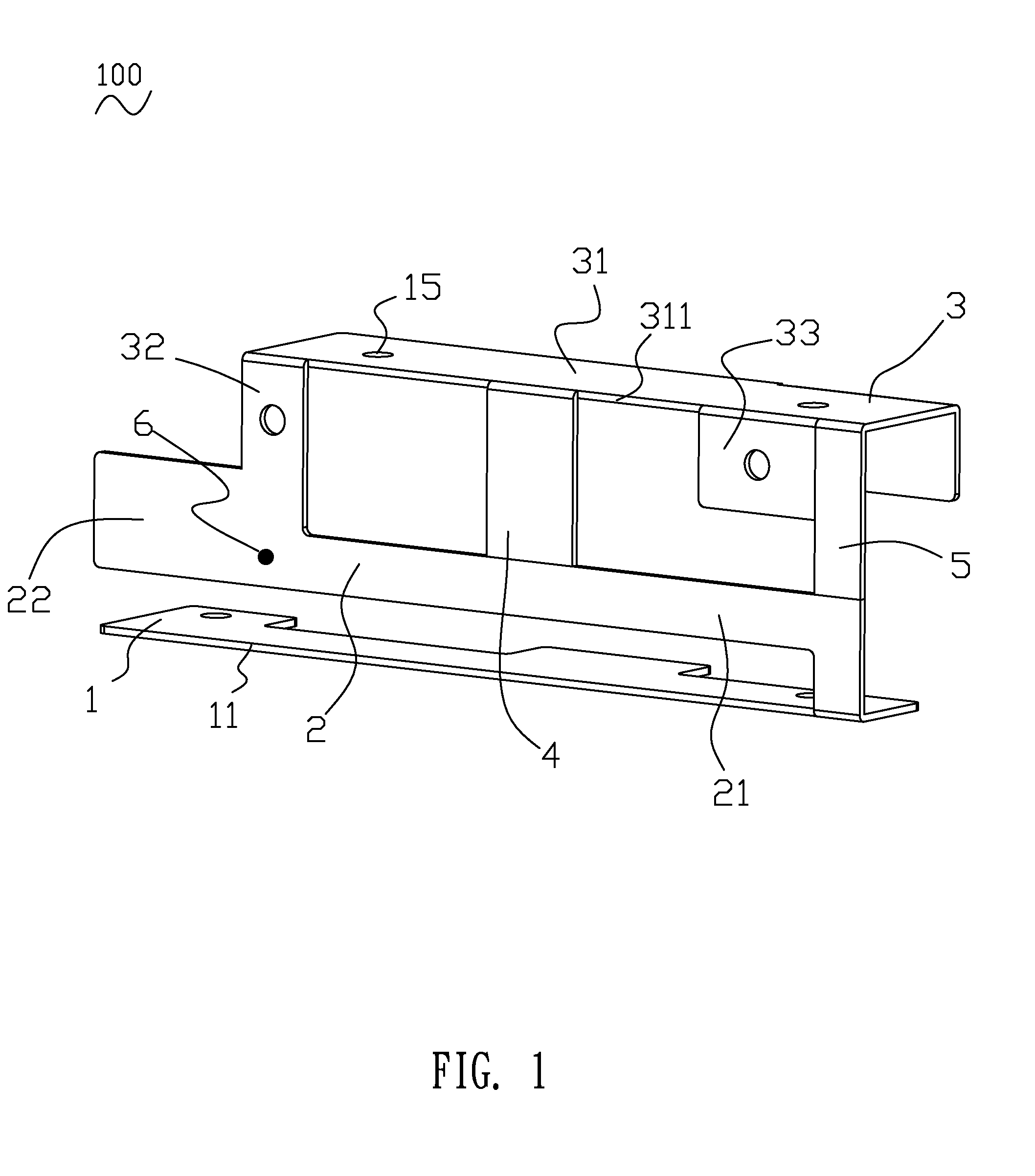
[0012]Please refer to FIG. 1, the embodiment of an ultra-wideband antenna 100 according to the present invention is shown. The ultra-wideband antenna 100, which may be punched from a sheet metal, includes an elongated grounding plate 1, a first antenna radiator 2, a second antenna radiator 3, a third antenna radiator 4, a connecting portion 5 and a feeding point 6.

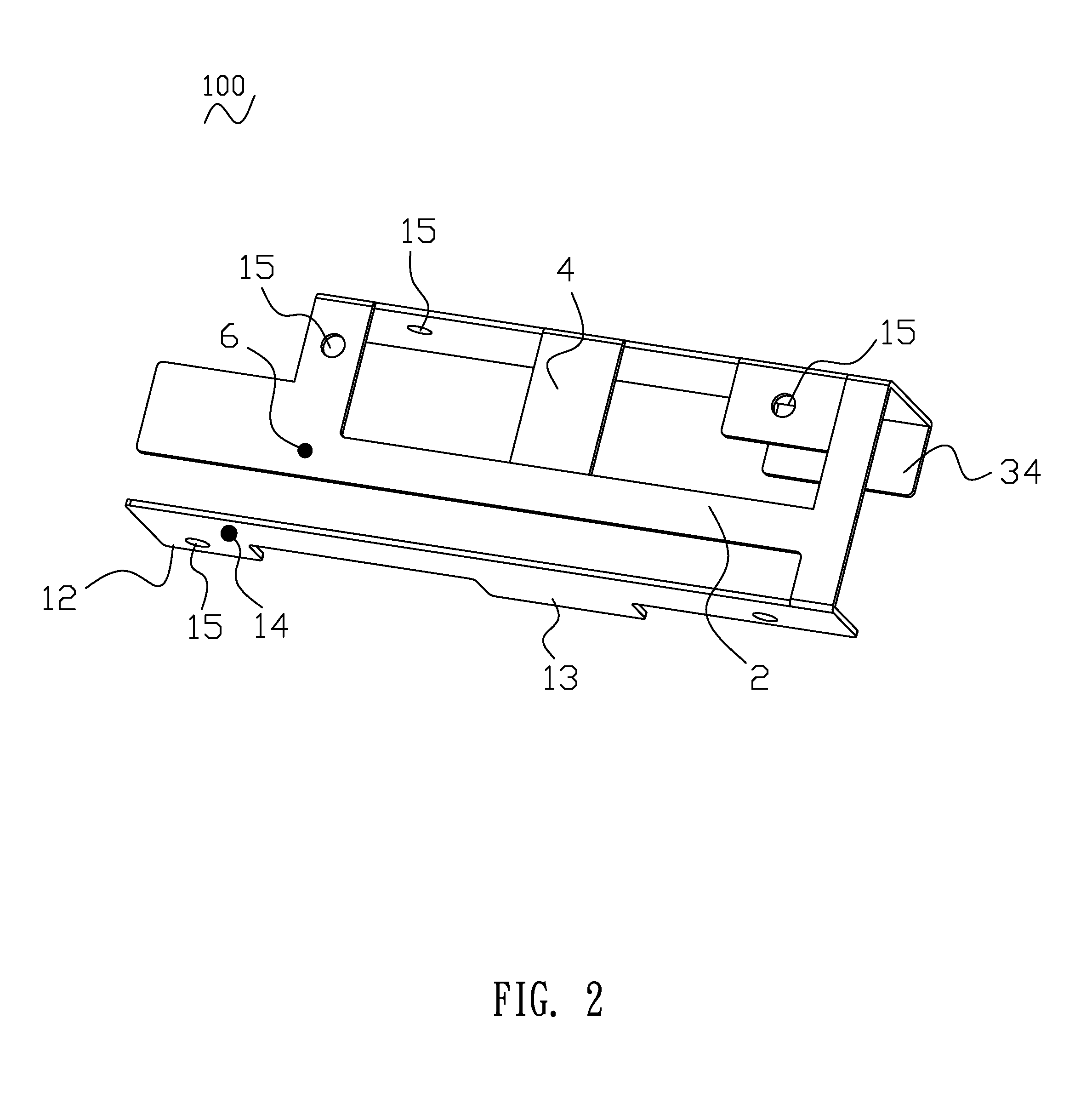
[0013]Please refer to FIG. 1 and FIG. 2, the grounding plate 1 is an elongated shape and disposed horizontally. A long side of the grounding plate 1 is defined a front edge 11. A rear edge of the grounding plate 1 opposite to the front edge 11 is extended rearward to form a first fixing portion 12 at an end thereof and a second fixing portion 13 at a middle portion thereof. The first fixing portion 12 and the second fixing portion 13 are spaced away from each other and capable of attaching with the electronic device (not shown). A grounding point 14 is disposed on a bottom of an end of the grounding plate 1 adjacent to the fi


PUM


Abstract

An ultra-wideband has an elongated grounding plate disposed horizontally with a long front edge defined thereon. A connecting portion extends upwards from an end of the front edge. A first antenna radiator includes a first radiating strip extended from a side of the connecting portion and a second radiating strip connecting with a free end of the first radiating strip. A third antenna radiator includes a third radiating strip suspended over the grounding plate, a fourth radiating strip connecting with an end of a long front edge of the third radiating strip and an upper side of the second radiating strip, a fifth radiating strip extended downwards from the long front edge of the third radiating strip connecting with the connecting portion. A third antenna radiator extends downwards from a middle of the long front edge of the third radiating strip. A feeding point disposes on the second radiating strip.

Description


Claims


Application Information

Patent Timeline
Owner CHENG UEI PRECISION IND CO LTD
Why Eureka
Try Eureka