Support assembling and locating sleeve

A technology of positioning sleeves and sets, which is applied in the direction of metal processing equipment, forming tools, manufacturing tools, etc., can solve the problems of no positioning device, too simple positioning method, and easy deviation in the positioning process, so as to achieve simple and compact structure and improve stability sexual effect

Inactive Publication Date: 2016-10-12
ZHENJIANG NAISI ADVANCE MATERIALS
View PDF7 Cites 0 Cited by
  • Summary
  • Abstract
  • Description
  • Claims
  • Application Information

AI Technical Summary

Problems solved by technology

[0002] In the production process of metal materials, the pre-deformed bracket needs to be positioned. There is no such positioning device

Method used


Image

  • Support assembling and locating sleeve
  • Support assembling and locating sleeve

Examples


Example Embodiment

[0013] The present invention will be further clarified below in conjunction with the drawings and specific embodiments.

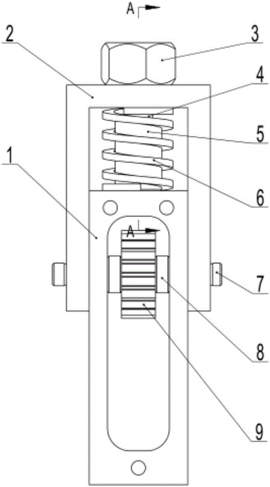
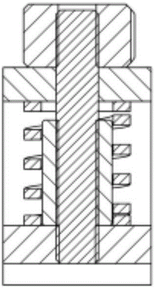
[0014] Such as Figure 1-2 As shown, the bracket is assembled with a positioning sleeve, including a pre-deformed bracket 1, a positioning sleeve 2, a nut 3, a screw 4, a nut bracket adjustment block 5, a spring 6, a shaft pin 7, a spacer 8 and a gear 9.

[0015] The positioning sleeve 2 is U-shaped, and the positioning sleeve 2 is sleeved on the pre-deformed support 1 through the shaft pin 7. After mating, the positioning sleeve 2 and the pre-deformed support 1 form an adjustment area; the gear 9 is set in the pre-deformed through the shaft pin 7 In the support 1, spacers 8 are provided on both sides of the gear 9.

[0016] A nut 3 is provided on the upper part of the positioning sleeve 2, and the nut 3 is fixed by a screw 4 passing through the positioning sleeve 2 into the adjustment area. A nut bracket adjustment block 5 is sleeved on the outer periphery of the s


PUM


Abstract

The invention discloses a support assembling and locating sleeve, and belongs to the technical field of metal wire production. The support assembling and locating sleeve comprises a pre-deformation support and a locating sleeve. The locating sleeve is arranged on the pre-deformation support in a sleeving manner through shaft pins. After cooperation, an adjustment area is formed between the locating sleeve and the pre-deformation support. A nut is arranged on the upper portion of the locating sleeve and fixed through a screw rod which penetrates the locating sleeve to enter the adjustment area. The periphery of the screw rod in the adjustment area is sleeved with a nut support adjusting block. A spring is arranged on the periphery of the nut support adjusting block. According to the support assembling and locating sleeve, the nut is arranged on the upper portion of the locating sleeve and fixed through the screw rod which penetrates the locating sleeve to enter the adjustment area; the periphery of the screw rod in the adjustment area is sleeved with the nut support adjusting block, and the spring is arranged on the periphery of the nut support adjusting block; and therefore the structure is simple and compact, a pre-deformer can be located conveniently and fast, and production stability is improved.

Description


Claims


Application Information

Patent Timeline
Owner ZHENJIANG NAISI ADVANCE MATERIALS
Why Eureka
Try Eureka