Short circuit protection device for rocket projectile storage and transportation launching box

A short-circuit protection and launch box technology, which is applied to coupling devices, parts of connecting devices, and devices for connecting/disconnecting connecting parts, etc., can solve the problems of difficult insertion and poor reliability, and achieve high safety, convenience and speed. Reliable effect of disassembly, short circuit effect

Active Publication Date: 2018-12-07
JINXI IND GRP
View PDF5 Cites 0 Cited by
  • Summary
  • Abstract
  • Description
  • Claims
  • Application Information

AI Technical Summary

Problems solved by technology

[0003] The purpose of the present invention is to provide a short-circuit protection device for rocket storage and launch boxes in

Method used


Image

  • Short circuit protection device for rocket projectile storage and transportation launching box
  • Short circuit protection device for rocket projectile storage and transportation launching box
  • Short circuit protection device for rocket projectile storage and transportation launching box

Examples


Example Embodiment

[0032] Example

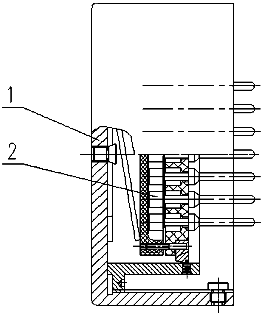
[0033] A short-circuit protection device for a rocket storage and launch box of the present invention, such as figure 1 As shown, it includes a protective cap 1 and a short-circuit body 2;

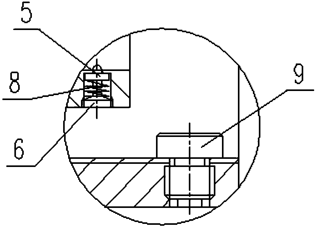
[0034] Among them, the protective cap 1 such as figure 2 , 3 As shown, it includes box cover 3, slotted screw 9, compression spring 4, ejector 5, spring 8, screw plug 6, ejector support 7;

[0035] The box cover 3 is a cylindrical structure with an open end, the inner wall of the box cover 3 is machined with internal threads, and the mouth side wall at the open end of the box cover 3 is provided with a set of evenly distributed screw holes on the circumference;

[0036] The mandrel bracket 7 is a cylindrical structure with an outer diameter smaller than the inner diameter of the box cover 3 and open at both ends. The outer wall of the left end of the mandrel bracket 7 has an annular connecting portion extending radially outward, and the outer wall of the annular connecting portion is


PUM


Abstract

The invention relates to a short circuit protection device for a rocket projectile storage and transportation launching box, and belongs to the technical field of projectiles and rockets. The short circuit protection device comprises a protection cap and a short circuit body. The protection cap comprises a box cover, a spiral groove screw, a compression spring, an ejecting rod, a spring, a screw plug and an ejecting rod support. The short circuit body comprises a supporting frame, a conductive disc, a pin cushion, pins, a bare wire, a pressing ring and long screw. According to the short circuit protection device, the split structure of the short circuit body and the protection cap is used so as to ensure that the short circuit protection device can be conveniently and quickly disassembledand assembled; the short circuit body is clamped by the compression spring and the ejecting rod in the protection cap so as to ensure the reliable conduction between all the pins and the conductive sheets. The short circuit protection device has reliable short circuit effect and high safety.

Description


Claims


Application Information

Patent Timeline
Owner JINXI IND GRP
Why Eureka
Try Eureka