Feeding machine with weighing system

A weighing system and feeder technology, applied in the field of feeders, can solve problems such as errors in hand measurement, death, affecting the growth of abalone, and achieve the effects of avoiding large errors, accurate feeding amount, and flexible and convenient selection.

Inactive Publication Date: 2018-12-11
张达英
View PDF5 Cites 0 Cited by
  • Summary
  • Abstract
  • Description
  • Claims
  • Application Information

AI Technical Summary

Benefits of technology

This patented describes a new type of feeder called Spinner® (registered trademark). These feeders have multiple tubular rows arranged sideways within them. Each row includes two parallel columns where different types of liquid may flow separately. One line supplies one end of the feedstock while another receives its own feed. A scanning mechanism helps keep track of these feedings and allows operators to manually change between different stations without stopping working. An oversized bowl is located at the bottom of the device's housing to improve accuracy and prevent overflowage. Toilets along with a rack serve as temporary restraint systems for workers who want access outside facilities like flooring tables. Power sources such as batteries and motors help deliver materials continuously over long distances.

Problems solved by technology

Technological Problem addressed in this patents relates to improving the accuracy and quickity of automatically feeding high quality seedling cultivations within big ocean areas where land resources cannot meet demand without overbuilding new facilities. Current solutions involve manually handling feeds through cabinets filled with ice blocks, making sure operators donate supplies during winter months when faced with lack of sunlight. However, these conventional approaches require significant effort and may result in incorrect measurements and reduced productivity rates. Therefore, technical means aim to provide devices capable of automating feeding processes while reducing staff intervention and increasing operational efficiency.

Method used


Image

  • Feeding machine with weighing system
  • Feeding machine with weighing system
  • Feeding machine with weighing system

Examples


Embodiment Construction

[0032] The technical solution of the present application will be further described in detail through the following embodiments in conjunction with the accompanying drawings. Apparently, the described embodiments are only part of the embodiments of the present application.

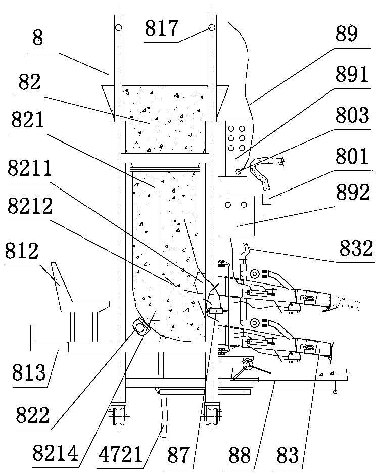
[0033] Such as image 3 , Figure 4 , Figure 5 As shown, it is a front view, a side view, and a partial enlarged view of a feeder with a weighing system according to the first embodiment of the present application. The feeder 8 includes a frame 81, a silo 82, and a hopper 821 , material injection pipe 83, material injection pipe lateral adjustment device 87, leaking material receiving device 88, weighing system 80, high-pressure gas distribution system 08, water flushing system 47, control system 89, and the frame 81 includes four columns 811 and the framework that cross bar constitutes, and the frame is provided with console 812 and storage platform 813, described frame below is provided with moving wheel


PUM


Abstract

The invention discloses a feeding machine with a weighing system, and the feeding machine comprises a frame, a stock bin, spraying pipes, the weighing system, an air pressure tank and a water pump. The upper part of the frame is connected with the stock bin, and one or more hoppers are connected in a vertical direction below the stock bin, wherein one or more hoppers are provided with transparentwindows. The spraying pipes are arranged and connected in the vertical direction of the hopper, and are arranged into one column or multiple columns, wherein the outlets of the spraying pipes are setin the same direction, and are set to be slightly horizontal in the lateral direction. The spraying pipes are provided with the weighing sensors, and the weighing system performs the weighing of the fodder to be thrown to the outside each time from the spraying pipes. The air pressure tank and the water pump are connected to the frame, and the water pump supplies water to the air pressure tank, and the air pressure tank can generate and store high-pressure water. The feeding machine throws the weighted fodder in the spraying pipes to the outside through taking the high-pressure water tas the power.

Description


Claims


Application Information

Patent Timeline
Owner 张达英
Why Eureka
Try Eureka