Method and device for automatic identification of abnormal channels

An automatic identification and abnormal channel technology, applied in the field of abnormal channel identification method and system, can solve problems such as time-consuming, large amount of calculation, complex algorithm, etc., and achieve the effect of rigorous and reliable theory, simple and practical operation process

Active Publication Date: 2018-12-14
CHINA PETROLEUM & CHEM CORP +1
View PDF4 Cites 0 Cited by
  • Summary
  • Abstract
  • Description
  • Claims
  • Application Information

AI Technical Summary

Problems solved by technology

The algorithms of these two methods are complex, computationally intensive, and time-consuming.

Method used


Image

  • Method and device for automatic identification of abnormal channels
  • Method and device for automatic identification of abnormal channels
  • Method and device for automatic identification of abnormal channels

Examples


Example Embodiment

[0040] Preferred embodiments of the present disclosure will be described in more detail below with reference to the accompanying drawings. While preferred embodiments of the present disclosure are shown in the drawings, it should be understood that the present disclosure may be embodied in various forms and should not be limited by the embodiments set forth herein. Rather, these embodiments are provided so that this disclosure will be thorough and complete, and will fully convey the scope of the disclosure to those skilled in the art.

[0041] Aiming at the problem of identifying abnormal traces of microseismic amplitude, the invention proposes an automatic identification method of abnormal traces based on Laida criterion.

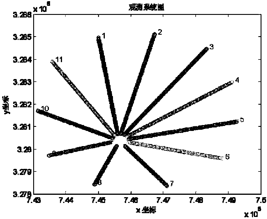
[0042] Specifically, as Image 6 As shown, the present invention discloses a method for automatically identifying abnormal tracks, the method comprising:

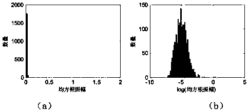
[0043] Calculate the rms amplitude of each trace in the seismic record;

[0044] taking the logarith


PUM


Abstract

The present invention provides a method and a device for automatic identification of abnormal channels. The method comprises the steps of: calculating the root mean square amplitude of each channel inseismic record; obtaining a logarithm of the root mean square amplitudes of the seismic channels; calculating the mean value and the standard deviation of the logarithm root mean square amplitudes; and comparing the logarithm root mean square amplitudes with the mean value, taking the logarithm root mean square amplitudes having deviation exceeding the standard deviation are abnormal values, andtaking the corresponding seismic channels as abnormal channels. The method and the device for automatic identification of abnormal channels can automatically identify the high-amplitude abnormal channels in the seismic channels, can identify abnormal values based on the statistics Pauta criterion, is reliable and strict in theory and simple and practical in operation flow, and provide help for identification of the microseismic events.

Description


Claims


Application Information

Patent Timeline
Owner CHINA PETROLEUM & CHEM CORP
Why Eureka
Try Eureka