Device capable of precisely simulating flow field of engine nacelle
An engine nacelle and flow field technology, which is applied in the direction of engine testing, measuring devices, machine/structural component testing, etc., can solve the problems of high cost and high engine cost, and achieve convenient manufacturing and use, and convenient integrated design , The effect of simple structure
- Summary
- Abstract
- Description
- Claims
- Application Information
AI Technical Summary
Benefits of technology
Problems solved by technology
Method used
Image

Examples
Embodiment 1
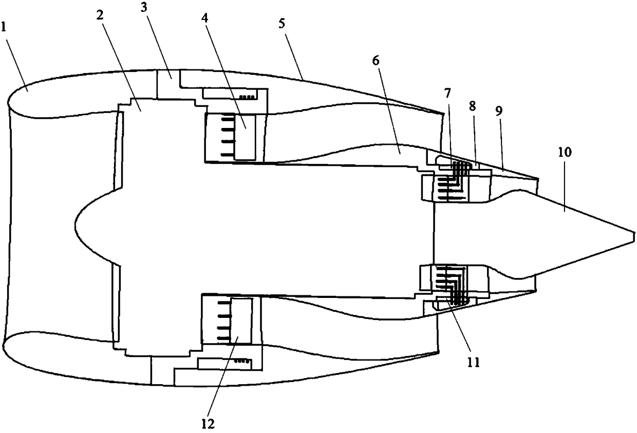
[0014] This embodiment provides a device capable of accurately simulating the flow field of the engine nacelle, which is characterized in that it includes the head of the culvert 1, the power simulator 2, the adapter 3 of the culvert, the measuring rake 4 of the culvert, and the tail of the culvert 5. Connotation main body 6, connotation measuring rake 7, inner covering plate 8, tail nozzle 9, tail vertebra 10, connotation measuring rake 11, and exoculum measuring rake 12;
[0015] Among them: the outer culvert head 1 and the outer culvert adapter 3 are connected by transverse screws and sealed by a sealing rubber ring; the power simulator 2 is connected to the outer culvert adapter 3 by longitudinal screws and sealed by a sealing rubber ring; The outer culvert measuring rake 4 is installed on the outer culvert adapter 3 through screws and sealant; the outer culvert tail 5 is connected to the outer culvert adapter 3 through transverse screws; the inner main body 6 is connected to
Embodiment 2
[0019] This embodiment provides a device capable of accurately simulating the flow field of the engine nacelle, which is characterized in that it includes the head of the culvert 1, the power simulator 2, the adapter 3 of the culvert, the measuring rake 4 of the culvert, and the tail of the culvert 5. Connotation main body 6, connotation measuring rake 7, inner covering plate 8, tail nozzle 9, tail vertebra 10, connotation measuring rake 11, and exoculum measuring rake 12;
[0020] Among them: the outer culvert head 1 and the outer culvert adapter 3 are connected by transverse screws and sealed by a sealing rubber ring; the power simulator 2 is connected to the outer culvert adapter 3 by longitudinal screws and sealed by a sealing rubber ring; The outer culvert measuring rake 4 is installed on the outer culvert adapter 3 through screws and sealant; the outer culvert tail 5 is connected to the outer culvert adapter 3 through transverse screws; the inner main body 6 is connected to
Embodiment 3
[0025] This embodiment provides a device capable of accurately simulating the flow field of the engine nacelle, which is characterized in that it includes the head of the culvert 1, the power simulator 2, the adapter 3 of the culvert, the measuring rake 4 of the culvert, and the tail of the culvert 5. Connotation main body 6, connotation measuring rake 7, inner covering plate 8, tail nozzle 9, tail vertebra 10, connotation measuring rake 11, and exoculum measuring rake 12;
[0026] Among them: the outer culvert head 1 and the outer culvert adapter 3 are connected by transverse screws and sealed by a sealing rubber ring; the power simulator 2 is connected to the outer culvert adapter 3 by longitudinal screws and sealed by a sealing rubber ring; The outer culvert measuring rake 4 is installed on the outer culvert adapter 3 through screws and sealant; the outer culvert tail 5 is connected to the outer culvert adapter 3 through transverse screws; the inner main body 6 is connected to
PUM
 Abstract
Description
Claims
Application Information
 - R&D Engineer
- R&D Manager
- IP Professional
- Industry Leading Data Capabilities
- Powerful AI technology
- Patent DNA Extraction
Browse by: Latest US Patents, China's latest patents, Technical Efficacy Thesaurus, Application Domain, Technology Topic.
© 2024 PatSnap. All rights reserved.Legal|Privacy policy|Modern Slavery Act Transparency Statement|Sitemap