Underwater propulsion device, underwater work equipment and movement control method thereof
A technology for underwater operations and propulsion devices, applied in the field of robotics, can solve problems such as increased power consumption, bulky propulsion devices, and inconvenient movement of underwater robots, and achieve the goals of reduced volume, flexible actions, and reduced power consumption Effect
- Summary
- Abstract
- Description
- Claims
- Application Information
AI Technical Summary
Problems solved by technology
Method used
Image

Examples
Embodiment 1
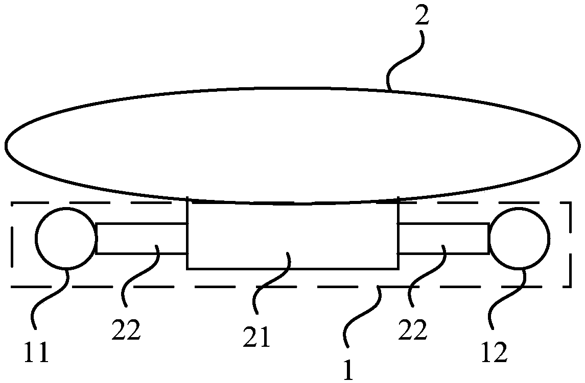
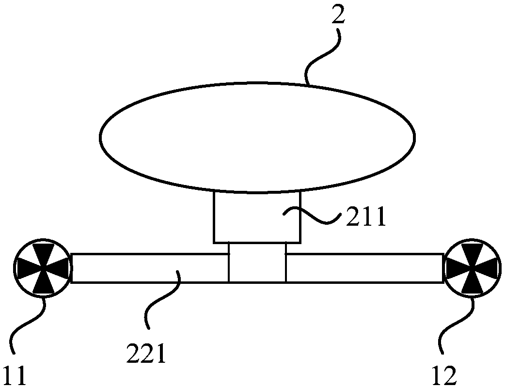
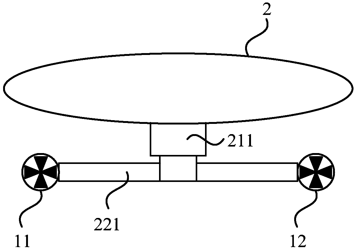
[0036] Figure 1a It is a schematic structural diagram of an underwater propulsion device provided in Embodiment 1 of the present invention. This embodiment is applicable to the situation where the underwater operation equipment performs multi-degree-of-freedom movement, and the underwater propulsion device 1 provided in this embodiment includes: a propulsion mechanism and a steering mechanism.
[0037] Wherein, the propulsion mechanism includes a first propulsion motor 11 and a second propulsion motor 12, the propulsion mechanism is arranged on the underwater operation equipment body 2, and is used to push the underwater operation equipment body 2 to move; the steering mechanism includes: steering gear 21 and a connecting rod 22, the steering gear 21 is connected to the first propulsion motor 11 and the second propulsion motor 12 through the connecting rod 22; the steering gear 21 is used to drive the propulsion mechanism to rotate around the output shaft of the steering gear 21
Embodiment 2
[0050] figure 2 It is a schematic structural diagram of an underwater control system provided by Embodiment 2 of the present invention. This embodiment is optimized on the basis of the above embodiments, and an optional underwater control system is provided. Specifically, the steering mechanism is further optimized.
[0051] The steering mechanism may specifically include: a fifth steering gear 215, a sixth steering gear 216 and a third connecting rod 223, the output shaft of the fifth steering gear 215 is fixedly connected to the sixth steering gear 216, and the output shaft of the fifth steering gear 215 Perpendicular to the output shaft of the sixth steering gear 216; the third connecting rod 223 runs through the output shaft of the sixth steering gear 216, and the axis of the third connecting rod 223 is arranged parallel to the output shaft of the sixth steering gear 216; the fifth steering gear The output shaft of 215 is arranged perpendicular to the axis of the third conn
Embodiment 3
[0063] image 3It is a schematic flowchart of a method for controlling movement of underwater operation equipment provided by Embodiment 3 of the present invention. The method is applicable to the situation of controlling the moving direction of the underwater working equipment, the method can be applied to the underwater working equipment described in the above embodiments, and is executed by a corresponding movement control module in the underwater working equipment. Specifically include the following:
[0064] S310. Obtain the target moving position of the underwater operation equipment.
[0065] In this embodiment, the target moving position may be the position information carried in the movement control command issued by the user, or the position information carried in the movement control command generated by other functional modules in the underwater operation equipment, which is not limited here. Wherein, the target moving position may be a designated destination positi
PUM
 Abstract
Description
Claims
Application Information
 - R&D Engineer
- R&D Manager
- IP Professional
- Industry Leading Data Capabilities
- Powerful AI technology
- Patent DNA Extraction
Browse by: Latest US Patents, China's latest patents, Technical Efficacy Thesaurus, Application Domain, Technology Topic.
© 2024 PatSnap. All rights reserved.Legal|Privacy policy|Modern Slavery Act Transparency Statement|Sitemap