Mold Movement Control Mechanism And Mold Having The Same

a technology of movement control mechanism and mold, which is applied in the field of control mechanism, can solve the problems of spring abrasion, corrosion, fatigue, and design difficulties of molds, and achieve the effects of reducing design and maintenance costs and improving product precision

Active Publication Date: 2018-07-19
SHEN YUAN PRECISION MOLD TECH CO LTD
View PDF0 Cites 0 Cited by
  • Summary
  • Abstract
  • Description
  • Claims
  • Application Information

AI Technical Summary

Benefits of technology

The invention relates to a mechanism that helps control the movements of a plate during injection molding processes. This eliminates the need for springs or other parts like pins, which saves money on manufacturing costs while improving product quality.

Problems solved by technology

This patent describes how control systems can help prevent damage caused by changes made during production. These systems use springs to push the plates of a mold in a way that ensures they stay within their designated paths. Additionally, these systems require specific ranges of force levels based on factors like injection pressure or molding pressure. Therefore, there needs to be some method to adjust the force level while keeping it precise.

Method used


Image

  • Mold Movement Control Mechanism And Mold Having The Same
  • Mold Movement Control Mechanism And Mold Having The Same
  • Mold Movement Control Mechanism And Mold Having The Same

Examples


Embodiment Construction

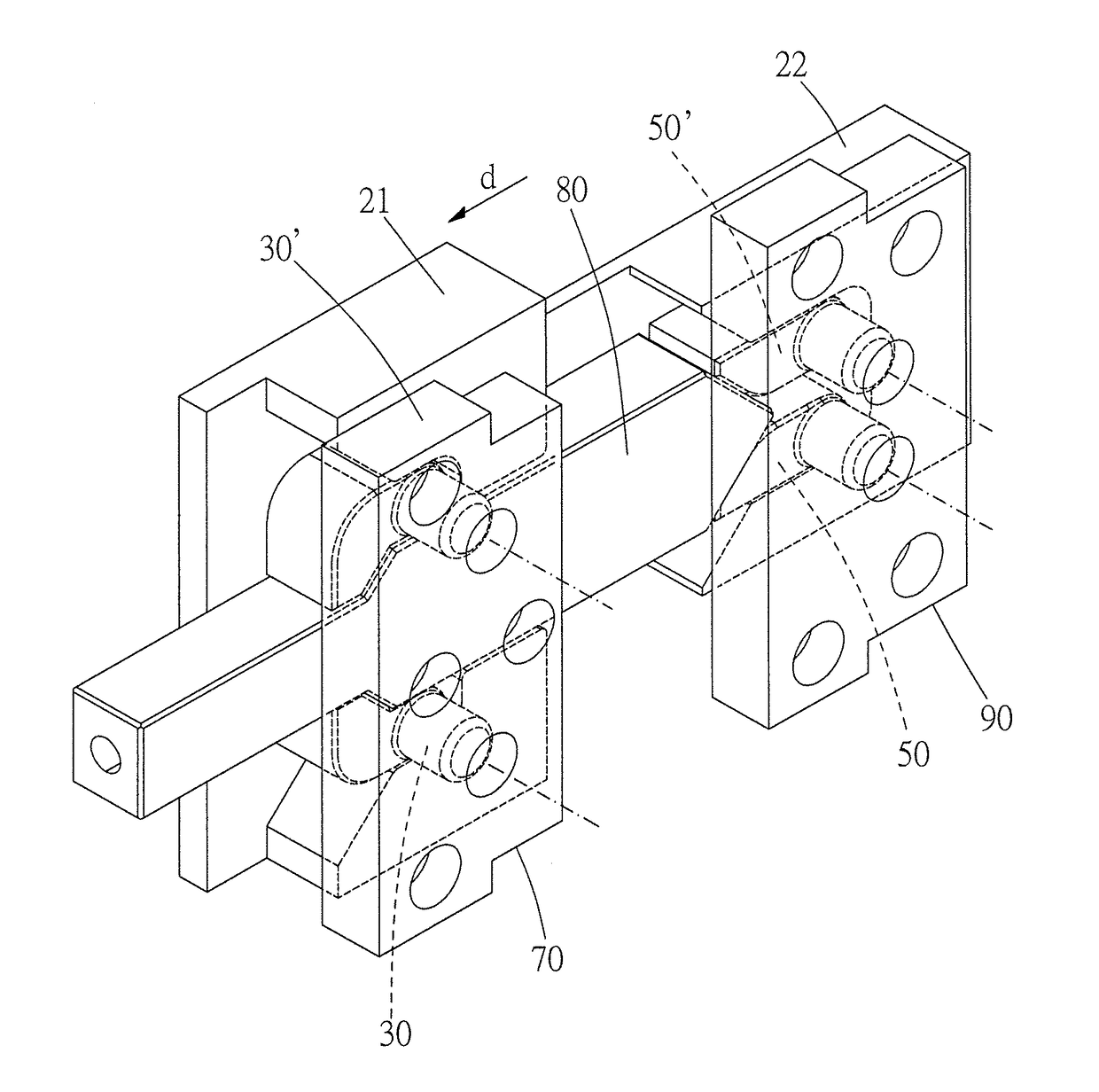
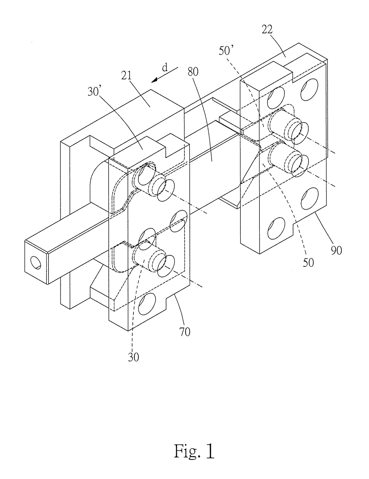
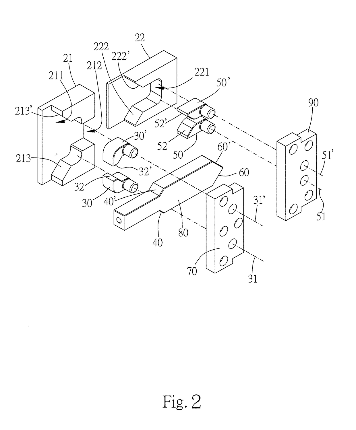
[0015]Please refer to FIG. 1 to FIG. 3 for an embodiment of the present invention. The present embodiment provides a mold movement control mechanism which is usually combined in a mold with a mold module. As shown in FIG. 3, the mold module includes a first plate 11, a second plate 12, and a third plate 13. The plates are components of the mold module which is utilized for molding works or products in manufacturing processes, such as injection molding process. The plates may be formed with cavities which contacts and receives the product directly in manufacturing processes. In other cases, the plates may be designed for carrying and controlling cores which are formed with cavities. Generally, the plates are made with flat appearance. However, the dimensions and the shape of the plates are not limited, adjustable for fitting with products and manufacturing machines. To remove or demould the product, the mold module can opened, closed, or moved by moving the mold module or the plates 11,


PUM

PropertyMeasurementUnit
Lengthaaaaaaaaaa
Torqueaaaaaaaaaa

Abstract

The present invention provides a mold movement control mechanism which is suitable for being assembled in mold to drive the plates of the mold to move. The mold movement control mechanism has a rotatable engaging member and two moving members. In one predetermined travel section, the engaging member is kept unable to rotate. The moving members are then engaged and moved together by the engaging member. After the moving members and the engaging member are moved across the predetermined travel section, the engaging member become rotatable, and the moving members are moved independently. Thus, the mold movement control mechanism can control the positions and travel paths of the moving members without spring. Manufacturing tolerance and maintenance cost could be both lowered.

Description


Claims


Application Information

Patent Timeline
Owner SHEN YUAN PRECISION MOLD TECH CO LTD
Why Eureka
Try Eureka