Vertical wind direction adjusting bracket

A technology of wind direction adjustment and tripod support, applied in the field of supports, can solve problems such as unfavorable normal operation of equipment, limited work efficiency, and inability to adjust the wind direction.

Pending Publication Date: 2018-12-25
GUANGDONG POWER GRID CO LTD +1
View PDF0 Cites 0 Cited by
  • Summary
  • Abstract
  • Description
  • Claims
  • Application Information

AI Technical Summary

Problems solved by technology

[0002] Some equipment, such as power station transformers or other electrical equipment, will generate a lot of heat during operation. If the heat is not dissipated, it will not be conducive to the normal operation of the equipment
At present, a large part of the equipment uses fans to dissipate heat, but

Method used


Image

  • Vertical wind direction adjusting bracket
  • Vertical wind direction adjusting bracket
  • Vertical wind direction adjusting bracket

Examples


Embodiment 1

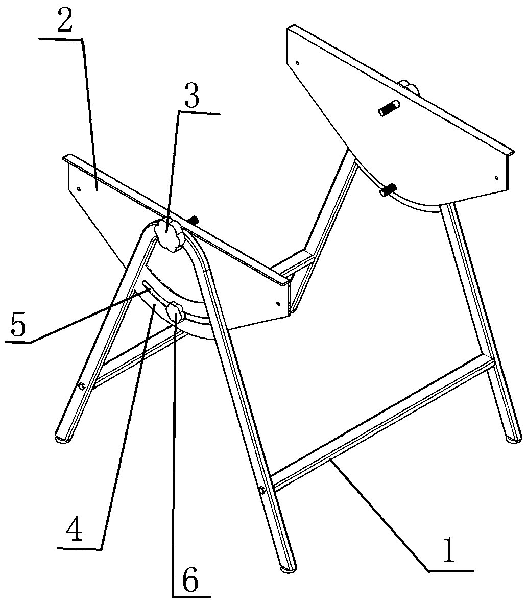
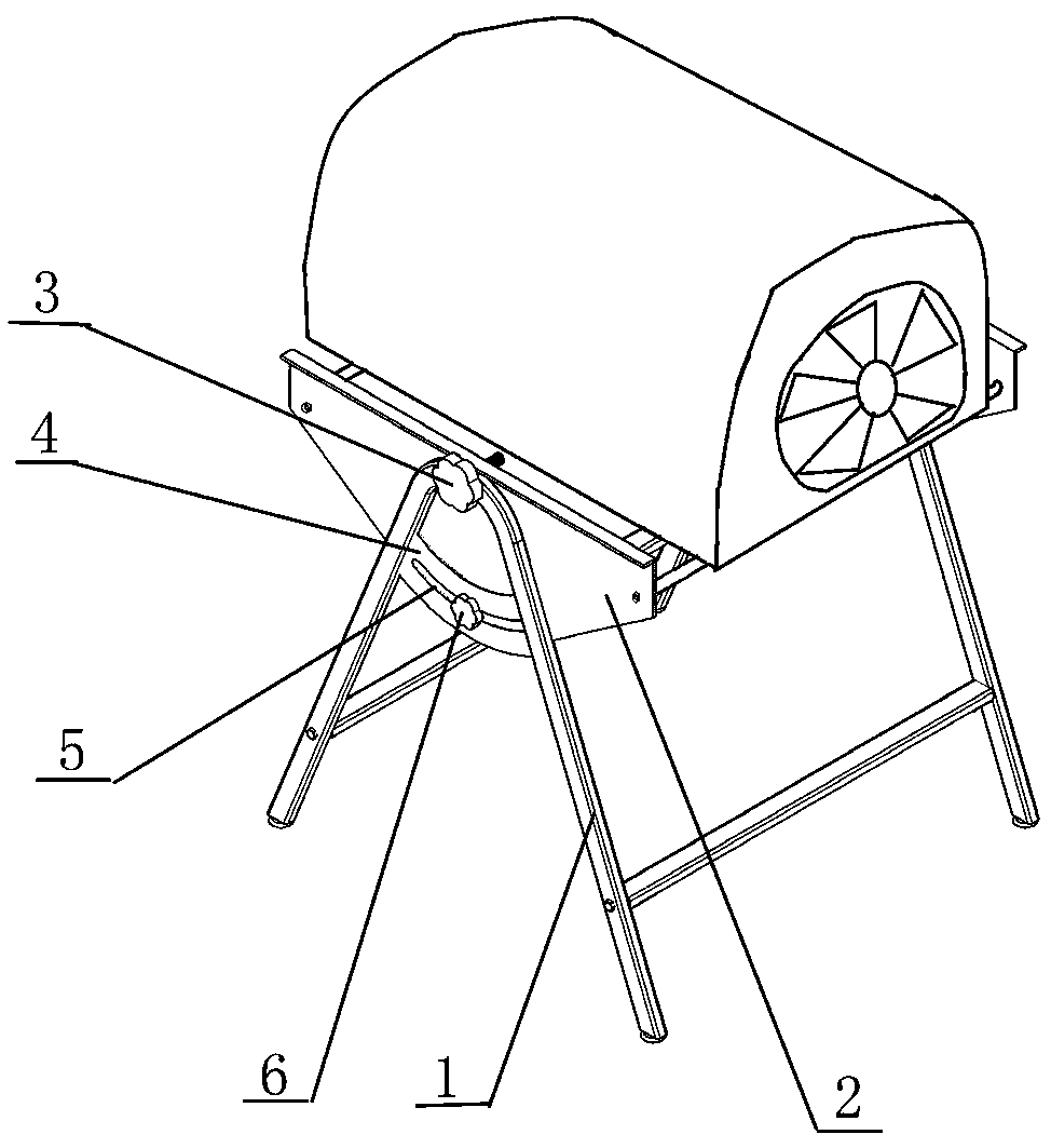
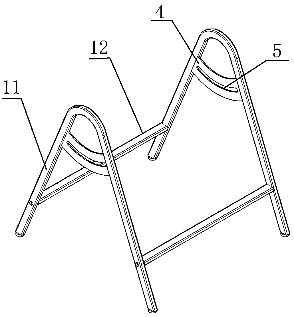
[0019] Such as figure 1 with figure 2 As shown, a vertical wind direction adjustment frame includes a bracket 1, and both sides of the bracket 1 are provided with a rotating plate 2 and a knob 3. The rotating plate 2 is fixed on the bracket 1 by the knob 3 and can rotate relative to the bracket 1 to dissipate heat. The fan is fixed between the rotating plates 2 on both sides of the bracket 1, the bracket 1 is provided with a horizontal plate 4, the horizontal plate 4 is provided with a groove 5, the rotating plate 2 is provided with locking bolts 6, and the locking bolts 6 pass through the grooves in turn 5. The rotating plate 2 and the nut are threaded.

[0020] Install the cooling fan between the two rotating plates 2 on the bracket 1, fix the cooling fan with the knob 3 and the nut, and make the cooling fan rotate relative to the bracket 1 with the knob 3 as the axis, when the cooling fan is rotated to a suitable angle , utilize the lock bolt 6 to cooperate with the nut to


PUM


Abstract

The invention relates to a bracket, in particular to a vertical wind direction adjusting bracket. The vertical wind direction adjusting bracket comprises a bracket; rotating plates and rotary knobs are arranged on the two sides of the bracket; the rotating plates are fixed on the bracket by the rotary knobs and can rotate relative to the bracket; a heat-dissipating fan is fixed between the rotating plates on the two sides of the bracket; the bracket is provided with a cross plate; the cross plate is provided with a groove; the rotating plates is provided with locking bolts; and the locking bolts sequentially pass through the groove and is in threaded connection with the rotating plates and nuts. By the vertical wind direction adjusting bracket, the heat-dissipating fan can be adjusted in avertical wind direction, so that the heat-dissipating fan is suitable for heat dissipation of various kinds of equipment and the heat-dissipating efficiency is improved.

Description


Claims


Application Information

Patent Timeline
Owner GUANGDONG POWER GRID CO LTD
Why Eureka
Try Eureka