Massive UI test generation method and device based on buried point data

A technology of test generation and point data, which is applied in the direction of program control device, electrical digital data processing, software testing/debugging, etc., and can solve problems such as poor simulation degree

Active Publication Date: 2018-12-28
挖财网络技术有限公司
View PDF4 Cites 2 Cited by
  • Summary
  • Abstract
  • Description
  • Claims
  • Application Information

AI Technical Summary

Problems solved by technology

[0006] In view of this, the purpose of the present invention is to address the above problems, to provide a mass UI test generation method and device based on buried point data, in order to solve the problem in the prior art that requires software testers to h

Method used


Image

  • Massive UI test generation method and device based on buried point data
  • Massive UI test generation method and device based on buried point data
  • Massive UI test generation method and device based on buried point data

Examples


Embodiment Construction

[0033] The present invention will be further described in detail below in conjunction with the accompanying drawings and examples. The following examples are explanations of the present invention and the present invention is not limited to the following examples.

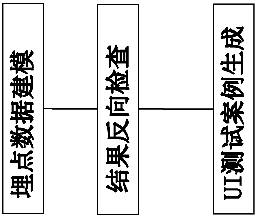
[0034] Such as figure 1 As shown, this massive UI test generation method based on buried point data includes: buried point data modeling, user data collection; result reverse check, to obtain a platform-independent test case model; UI test case generation, buried point data Data output from modeling and result backchecks as test cases

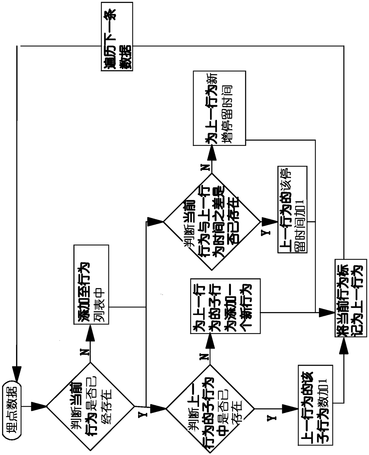
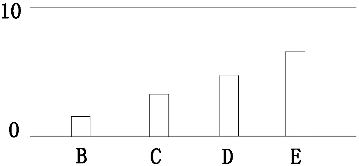
[0035] Specifically, in the buried point data modeling here, the user behavior probability histogram and the dwell time probability histogram are obtained; the user behavior probability histogram and the dwell time probability histogram here are for unified user behavior; the buried point here The collection of user data in data modeling includes the capture, processing, transmission


PUM


Abstract

The invention provides a massive UI test generation method based on buried point data and a device thereof, belonging to the technical field of software test. The invention solves the problems of irrational design of the prior art and the like. The invention relates to a mass UI test generation method and a device thereof based on buried point data, which comprises the following steps: buried point data is modeled and user data is collected; the platform-independent test case model is obtained by result backward checking; UI test cases are generated, and the data output from buried point datamodeling and result reverse check is used as test cases. The advantages of the mass UI test generation method based on buried point data and the device thereof are that the problem that the PIT overlyrelies on the PIM is solved, and the PIT can simulate the user behavior to a high degree.

Description


Claims


Application Information

Patent Timeline
Owner 挖财网络技术有限公司
Why Eureka
Try Eureka