Continuous feeding and stamping apparatus for bottle cap production

A stamping equipment and bottle cap technology, which is applied in the field of continuous feeding stamping equipment for bottle cap production, can solve the problems of low equipment cooperation, poor stamping effect, waste of labor precision of workers, etc., to improve stamping efficiency, improve stamping effect, The effect of enhancing coordination

Inactive Publication Date: 2019-01-04
安徽省潜山县包装制品有限公司
View PDF5 Cites 4 Cited by
  • Summary
  • Abstract
  • Description
  • Claims
  • Application Information

AI Technical Summary

Benefits of technology

In this new device, it uses multiple components like motors or gears instead of just one component used alone to control movement during machining operations. By adding these components, the machine can perform more precise movements without being affected by external factors such as temperature changes or vibrations caused from other machines. Overall, this technology enhances the performance and functionality of existing tools while reducing their size and weight.

Problems solved by technology

This patented technical problem addressed by this patents relates to improving the efficiency and accuracy required when producing bottles' lids from paper or other material that can vary significantly depending upon factors like temperature and humidity levels. Existing methods require high skill level operators who have limited ability to perform repetitive movements accurately due to their lack of continuance over multiple cycles. Additionally, existing solutions only work well within specific ranges based on certain conditions such as pressure applied while pressing onto the blanket surface.

Method used


Image

  • Continuous feeding and stamping apparatus for bottle cap production
  • Continuous feeding and stamping apparatus for bottle cap production
  • Continuous feeding and stamping apparatus for bottle cap production

Examples


Embodiment Construction

[0018] The following will clearly and completely describe the technical solutions in the embodiments of the present invention with reference to the accompanying drawings in the embodiments of the present invention. Obviously, the described embodiments are only some, not all, embodiments of the present invention. Based on the embodiments of the present invention, all other embodiments obtained by persons of ordinary skill in the art without making creative efforts belong to the protection scope of the present invention.

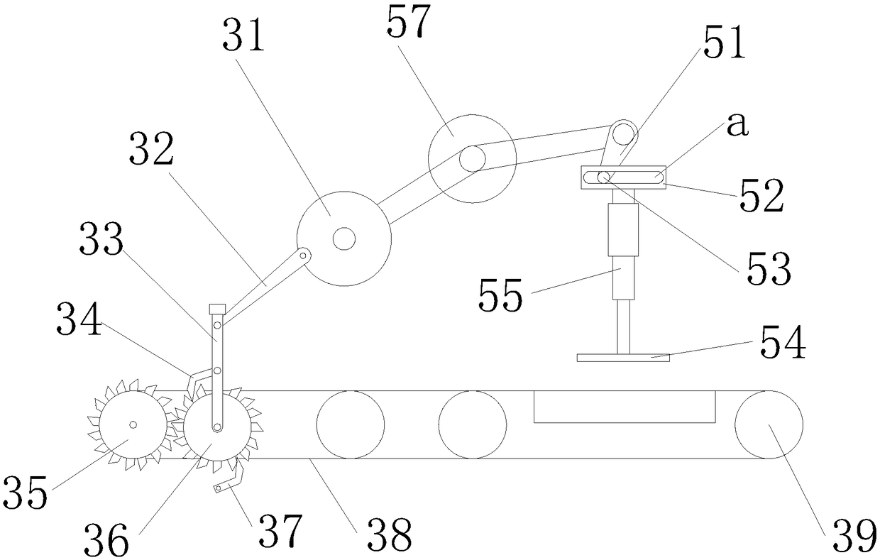
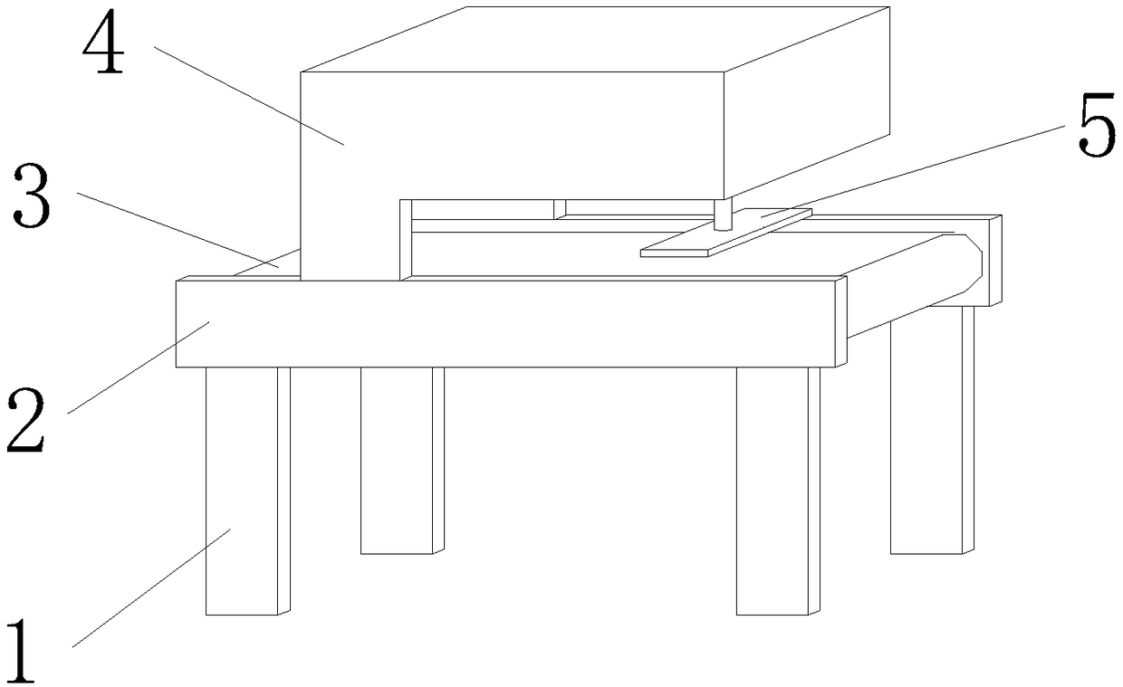
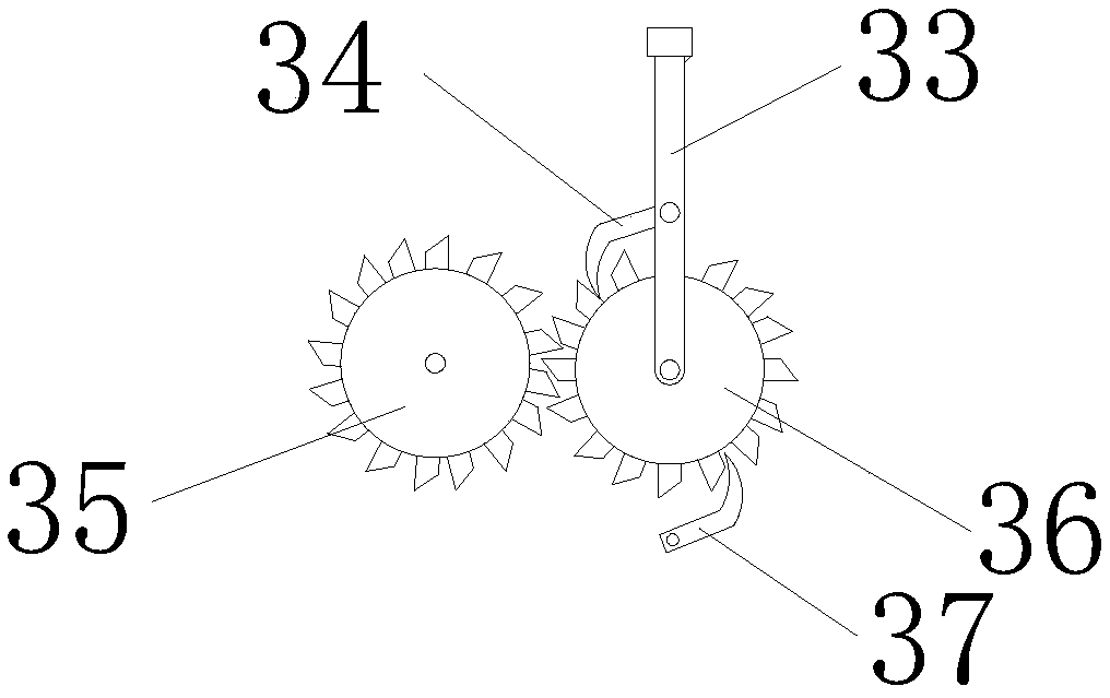
[0019] see Figure 1-4 , the present invention provides a technical solution: a continuous feeding stamping equipment for bottle cap production, including a device main body, an intermittent motion mechanism 3 and a stamping mechanism 5, the device main body includes a leg 1, a support frame 2 and a mounting bracket 3, and supports The frame 2 is arranged on the top of the support leg 1, and the mounting bracket 3 is arranged on the top of the supporting frame 2.


PUM


Abstract

A continuous feeding and stamping apparatus for bottle cap production includes a turntable, a drive lever, a first swing lever, a drive pawl, an active ratchet shaft, a drive belt, a roller, a secondswing lever, a drive block, a drive ball, a stamping head, a guide lever and a drive motor, the drive belt coats the outer surface of the active ratchet shaft and the roller, the low end of the firstswing lever is rotatably connected with the center position of the front face of the active ratchet shaft, the drive pawl engages with the active ratchet shaft, the right end of that drive lever is rotatably connected with a hinge shaft of an out ring of the front end face of a rotary table, the above design drives the metal raw material to continuously move to the lower side of the stamping head, at the same time, there is a short intermittent time for punching operation, the top end of the second swing rod is fixed on the drive shaft, the drive ball is arranged on the bottom end of the second swing rod, and the transmission ball is located in a groove, the stamping head is fixedly connected with the guide lever, and the guide lever is fixed on the lower end of the drive block. The design improves the stamping effect, improves the stamping efficiency, and strengthens the coordination degree of the equipment mechanism.

Description


Claims


Application Information

Patent Timeline
Owner 安徽省潜山县包装制品有限公司
Why Eureka
Try Eureka