High-load stepless dimming control device and dimming system for application thereof

A stepless dimming and control device technology, applied in lighting devices, light sources, electric light sources, etc., can solve the problems of easy safety accidents, complicated installation and wiring, and high investment costs, and achieve easy promotion, low input costs, and easy installation. and the effect of simple wiring

Active Publication Date: 2019-01-08
SICHUAN PENGTIAN TECH DEV
View PDF14 Cites 0 Cited by
  • Summary
  • Abstract
  • Description
  • Claims
  • Application Information

AI Technical Summary

Benefits of technology

This patented technology allows for efficient use of power during different types of lights being driven on an electronic product (such as LED lamps). It also includes a system where each lamp receives its own programmable controller unit(PLC) which controls how much electricity flows into them based upon their specific needs. By sending signals from the PLC back to the Lamp driver circuits, they adjust the brightness level accordingly without requiring any extra equipment or complicated installations. Overall, these technical improvements improve efficiency and effectiveness over existing methods used previously.

Problems solved by technology

Technological Problem: The technical problem addressed in this patented text relates to improving the efficiency and accuracy of road networks that use multiple lanings within their interior walls without causing dark areas during peak hours when vehicles drive downwardly towards them. Current methods involve installing dimming controls throughout these roads which require significant labor costs and can lead to issues such as insufficient visibility caused by sunlight glare.

Method used


Image

  • High-load stepless dimming control device and dimming system for application thereof
  • High-load stepless dimming control device and dimming system for application thereof
  • High-load stepless dimming control device and dimming system for application thereof

Examples


Embodiment Construction

[0019] The present invention will be further elaborated below in conjunction with the accompanying drawings.

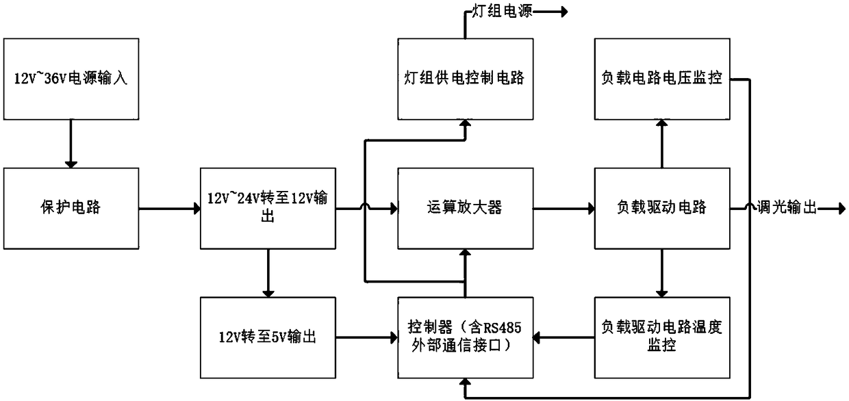
[0020] refer to figure 1 As shown, one embodiment of the present invention is a high-load stepless dimming control device, which includes a microprocessor, and the microprocessor can use a single-chip microcomputer with data processing and communication functions; the microprocessor is connected to Power module, and the microprocessor is also connected to the load driving circuit through the operational amplifier, and the operational amplifier also needs to be connected to the power module, and the power module is input by the voltage of 12-36V; the aforementioned load driving circuit is used to connect to the lighting device ; The load driving circuit can drive the loads of multiple lighting devices through a high load, and then use one load driving circuit to drive multiple lighting devices;

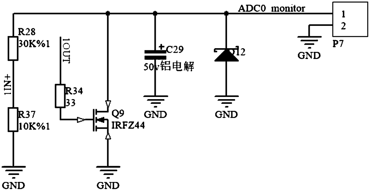
[0021] The structure of the load driving circuit in this embodiment is as f


PUM


Abstract

The invention discloses a high-load stepless dimming control device and a dimming system for application thereof. The device comprises a microprocessor, a microprocessor connected with a power supplymodule, and the microprocessor is connected with a load driving circuit through an operational amplifier, and the operational amplifier is also connected with a power supply module. A load drive circuit is use for accessing that light device; The load driving circuit is connected with the voltage monitoring module and the temperature monitoring module respectively, and the voltage monitoring module and the temperature monitoring module are connected with the microprocessor. The microprocessor includes an external communication interface. The operational amplifier comprises a filter module; Byproviding a load driving circuit with a high load in the device, the load driving circuit can support the load driving of a plurality of lighting devices, so that only one dimming control device can be used for the plurality of lighting devices to complete the dimming, and the installation and the tracing are simple and the input cost is low.

Description


Claims


Application Information

Patent Timeline
Owner SICHUAN PENGTIAN TECH DEV
Why Eureka
Try Eureka