Mechanical transmission structure of electronic booster

A technology of mechanical transmission and booster, applied in the direction of brake transmission, brake, transportation and packaging, can solve problems such as failure of automobile brakes, and achieve the effect of convenient operation and simple structure

Pending Publication Date: 2019-01-11
SHIJIAZHUANG JIAXIN AUTOMOTIVE BRAKE SYST
View PDF6 Cites 0 Cited by
  • Summary
  • Abstract
  • Description
  • Claims
  • Application Information

AI Technical Summary

Problems solved by technology

[0003] The purpose of the present invention is to provide a mechanical transmission structure of an electronic booster to solve the prob...

Method used


Image

  • Mechanical transmission structure of electronic booster
  • Mechanical transmission structure of electronic booster

Examples


Embodiment Construction

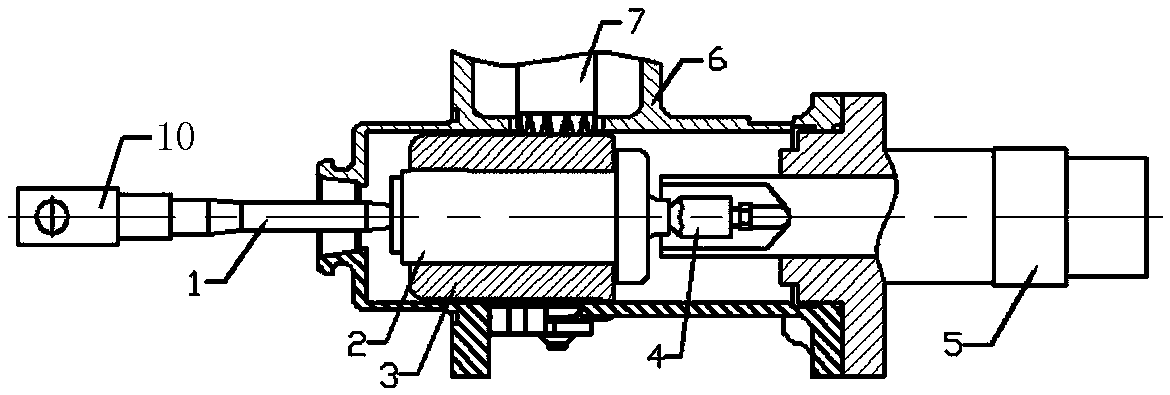
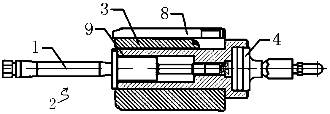
[0021] like figure 1 and figure 2 As shown, the mechanical transmission structure of the electronic booster of the present invention includes a cylinder block 6, a motor booster mechanism 7 arranged on the cylinder block, a valve body assembly 2, a gear sleeve 3 and a sensor 8 arranged inside the cylinder block 6, and A controller (not shown in the figure) connected to the motor assist mechanism 7 .

[0022] The cylinder block 6 is a horizontal cylinder barrel, one end of the cylinder barrel is provided with a push rod inlet, and the other end is provided with a brake master cylinder inlet. The valve body assembly 2 is arranged inside the cylinder along the axial direction of the cylinder, and the valve body assembly 2 can move along the axial direction of the cylinder under the action of external force. The valve body assembly 2 includes a valve body 9 , a push rod 1 and an output rod 4 . The valve body 9 is a hollow tubular structure, the gear sleeve 3 is set on the peri...


PUM


Abstract

The invention provides a mechanical transmission structure of an electronic booster. The mechanical transmission structure of an electronic booster comprises a cylinder, an electric motor booster mechanism on the cylinder, a valve assembly inside the cylinder, a gear sleeve, a sensor, and a controller connected with the electric motor booster mechanism. The valve assembly is axially disposed within the cylinder tube of the cylinder. The valve assembly comprises a valve body, a push rod and an output rod, wherein the front end of the valve body is connected with the end of the push rod, and theend of the valve body is connected with the front end of the output rod, and the front end of the push rod is connected with the brake pedal, and the end of the output rod is connected with the brakemaster cylinder. The gear sleeve is arranged on the periphery of the valve body and abuts on the mesa of the boss on the outer wall of the end of the valve body. The connection mode enables the gearsleeve to drive the whole valve assembly to move along the axial direction of the end, and the valve assembly can move along the axial direction of the end without the gear sleeve after being forced.The mechanical transmission structure of an electronic booster is used for an electronic intelligent boosting system driven by a motor, and can play a boosting role when the boosting system works normally. The brake system can also be used to complete the brake when the booster system is abnormal or malfunctioning.

Description

technical field [0001] The invention relates to a mechanical transmission structure, in particular to a mechanical transmission structure for a vehicle electronic booster. Background technique [0002] The development and production of automobile vacuum boosters in my country began in the early 1980s, and the reaction disc vacuum boosters have been recognized and widely used by the market today. With the development of society, the configuration of cars is getting higher and higher, such as the emergence of ABS, EBD, ESC and other functions, automatic parking and driverless driving are also on the agenda, but it is difficult for vacuum boosters to actively control them, and Due to the structural reasons of the vacuum booster, the realization of intelligence has not been very ideal, but the electronic intelligent booster system and the manufacturing technology of its booster components can meet the requirements of intelligence. In the prior art, the electronic intelligent bo...

Claims


Application Information

Patent Timeline
Patent Type & Authority Applications(China)
IPC IPC(8): B60T13/74
CPCB60T13/74
Inventor 李建忠
Owner SHIJIAZHUANG JIAXIN AUTOMOTIVE BRAKE SYST
Why Eureka
Try Eureka