Welding line positioning method and system applied to welding line positioning

A positioning method and image technology, applied in welding equipment, laser welding equipment, metal processing equipment, etc., can solve the problems of poor welding accuracy of sheet folding, and achieve the effect of improving welding quality, solving positioning inaccuracy, and improving positioning accuracy.

Inactive Publication Date: 2019-01-15
HANS LASER TECH IND GRP CO LTD +1
View PDF3 Cites 6 Cited by
  • Summary
  • Abstract
  • Description
  • Claims
  • Application Information

AI Technical Summary

Benefits of technology

This new technology helps improve the alignment during joining processes by providing an accurate way for it to be aligned with other parts on the same part being joined together without any mistakes or errors.

Problems solved by technology

This patented describes different technical problem areas for implementing precise and reliable laser beam weldings (LFW) processes such as plate foldable or tube winding techniques. These methods have limitations when applied to various fields where strict requirements exist over their performance characteristics. Additionally, these methods can lead to poorly controlled weld patterns which could result from incorrect placement of the lasers' spots within specific locations. There needs to provide better ways to track and locate the positions of the LFW welds accurately without any issues like mispositioning or insufficient overlap between them.

Method used


Image

  • Welding line positioning method and system applied to welding line positioning
  • Welding line positioning method and system applied to welding line positioning
  • Welding line positioning method and system applied to welding line positioning

Examples


Embodiment Construction

[0024] In order to facilitate the understanding of the present invention, the present invention will be described more fully below with reference to the associated drawings. Preferred embodiments of the invention are shown in the accompanying drawings. However, the present invention can be embodied in many different forms and is not limited to the embodiments described herein. On the contrary, these embodiments are provided to make the understanding of the disclosure of the present invention more thorough and comprehensive.

[0025] Unless otherwise defined, all technical and scientific terms used herein have the same meaning as commonly understood by one of ordinary skill in the technical field of the invention. The terms used herein in the description of the present invention are for the purpose of describing specific embodiments only, and are not intended to limit the present invention.

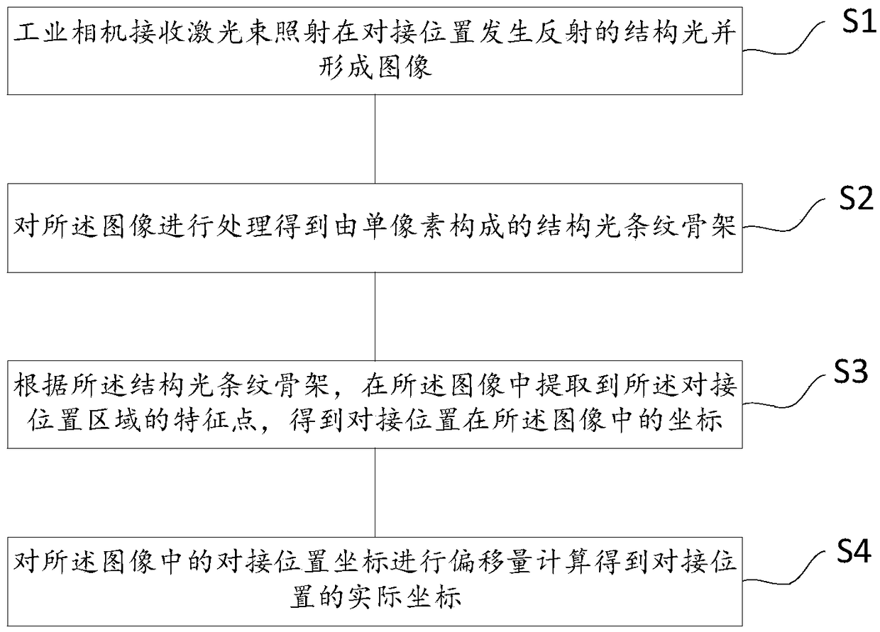
[0026] refer to figure 1 , the embodiment of the present invention provides a welding


PUM


Abstract

The embodiment of the invention discloses a welding line positioning method for positioning the butt joint position between welding workpieces. The welding line positioning method comprises the stepsthat an industrial camera receives structured light reflected through laser beam irradiation at the butt joint position, and an image is formed; the image is processed, and a structured light stripe framework composed of single pixels is obtained; according to the structured light stripe framework, feature points of the butt joint position area are extracted from the image, and coordinates of thebutt joint position in the image are obtained; and deflection amount calculation is conducted on the butt joint position coordinates in the image, and the actual coordinates of the butt joint positionare obtained. Through the above manner and the implementing manner, the problem that in the prior art, positioning of the butt joint position of the middle of a folded welding workpiece is inaccurateis solved; and through the positioning method, the positioning precision is improved, the later welding operation is facilitated, and the welding quality is improved.

Description


Claims


Application Information

Patent Timeline
Owner HANS LASER TECH IND GRP CO LTD
Why Eureka
Try Eureka