Mechanism for fixing slip fishing cylinder

A technology for fixing slips and overshots, applied to parts of bottles/cans, rigid containers, containers, etc., can solve problems such as damage, and achieve the effect of facilitating the rotation of the supporting screw

Inactive Publication Date: 2019-01-18
德阳行之德智知识产权运营有限公司
View PDF0 Cites 1 Cited by
  • Summary
  • Abstract
  • Description
  • Claims
  • Application Information

AI Technical Summary

Benefits of technology

This new design allows for better stability by keeping both the slinger's threaded end fixed on one side while being secured at another location along its length. It prevents this movement that could cause collisions between the carrier boxes or other items inside them. Additionally, there may be protective features like covers placed around the threads to keep these parts clean before use again after they have been used once more. Overall, this technology ensurizes stable handling without damaging any objects within their carriers.

Problems solved by technology

This patented technical problem addressed by this patents relates to improving the durability or lifespan of slipovershots for various purposes such as fishermen's chasing outflies.

Method used


Image

  • Mechanism for fixing slip fishing cylinder
  • Mechanism for fixing slip fishing cylinder
  • Mechanism for fixing slip fishing cylinder

Examples


Embodiment 1

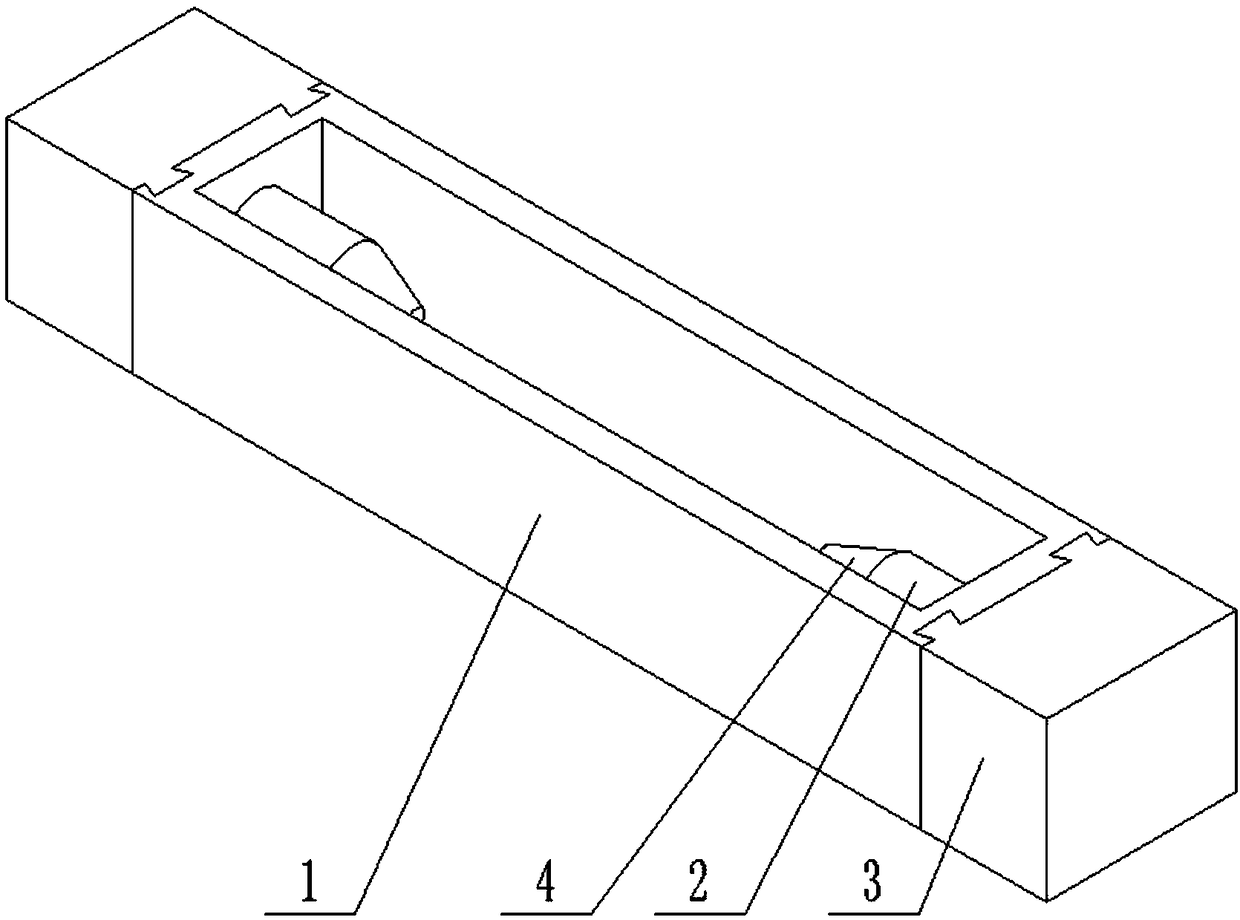
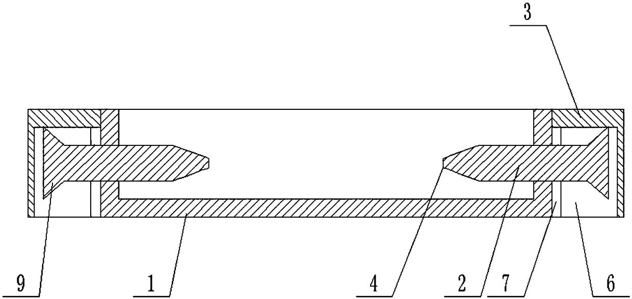
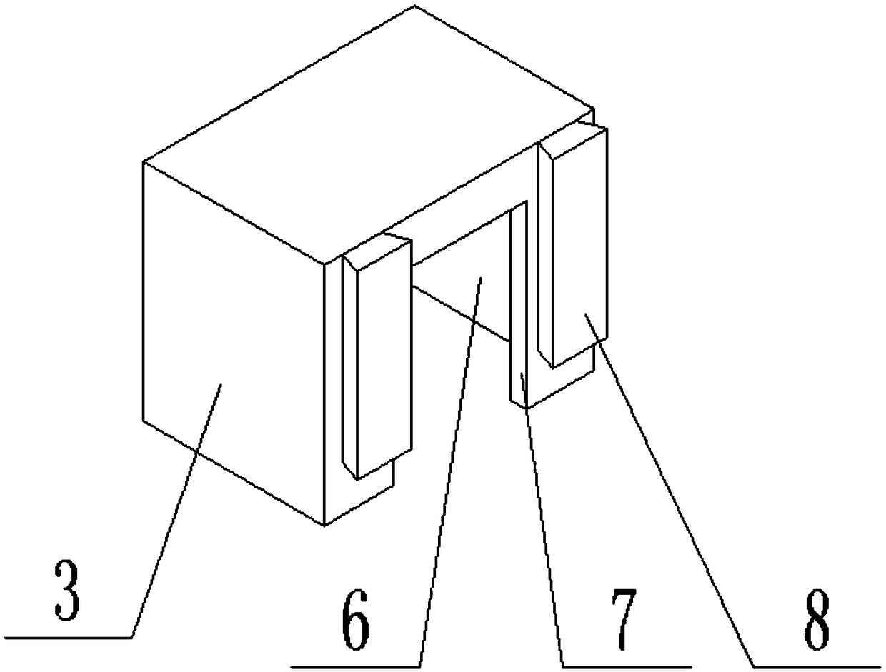
[0025] like Figure 1-Figure 4 As shown, the mechanism for fixing the slip overshot of the present invention includes a bearing box 1, a support screw 2, and a cover block 3. A pair of opposite box walls of the bearing box 1 are provided with threaded holes whose axes coincide with each other. The supporting screw rods 2 are threadedly connected with a threaded hole respectively, and the opposite surfaces of the supporting screw rods 2 are provided with a round table 4, the large end face of the round table 4 is connected with the screw rod 2, and the axis of the round table 4 is connected with the supporting screw rod 2. The axis coincides;

[0026] A chute 5 is provided on the outer surface of the threaded hole on the carrier box 1, the opening size of the chute 5 is smaller than the bottom size of the groove, and the extension axis of the chute 5 is perpendicular to the bottom of the carrier box 1, which One end close to the bottom of the box is a closed end, and the other en

Embodiment 2

[0032] This embodiment is based on Embodiment 1 to further illustrate the present invention.

[0033] like figure 2 and Figure 4 As shown, the mechanism for fixing the slip overshot of the present invention is provided with a rotating plate 9 at the end of the supporting screw 2 away from the round platform 4 , and the rotating plate 9 is parallel to the axis of the supporting screw 2 .

[0034] The setting of the rotating plate 9 is convenient for rotating the supporting screw rod 2 to save effort.

[0035] Preferably, the rotating plate 9 is an isosceles trapezoidal plate, and the end surface where the upper bottom is located is connected with the support screw 2 .

Embodiment 3

[0037] This embodiment is based on Embodiment 1 to further illustrate the present invention.

[0038] like Figure 4 As shown, in the mechanism for fixing the slip overshot of the present invention, the chute 5 is a dovetail groove. Chute 5 can also adopt T-shaped groove.


PUM


Abstract

The invention discloses a mechanism for fixing slip fishing cylinder, which comprises a bearing box, supporting screw rods and covering blocks, wherein threaded holes are arranged at a pair of opposite box walls of the bearing box, and the supporting screw rods are connected with a thread hole respectively. The supporting screw rods are provided with circular tables on the opposite surfaces of each other. The end face of the big end of the round table is connected with a screw rod; sliding grooves are arranged on the outer surface of the threaded holes on the bearing box, and the opening sizeof the sliding groove is smaller than that of the groove bottom; a groove is arranged at the bottom of the covering block, and a notch communicated with the groove is arranged on one side wall of thecovering block. A sliding block matched with the sliding groove is arranged on the side wall provided with a notch on the covering block. The number of the covering block is two. One end of the supporting screw rods far away from the round table are respectively passed through a gap and are positioned in the groove. The mechanism for fixing slip fishing cylinder prevents the slip fishing cylinderfrom moving oppositely to the bearing box to produce a collision during transportation.

Description


Claims


Application Information

Patent Timeline
Owner 德阳行之德智知识产权运营有限公司
Why Eureka
Try Eureka