A modeling method of energy distributor based on bus structure

A technology of energy distributor and modeling method, applied in instruments, special data processing applications, electrical digital data processing, etc., can solve problems such as optimal allocation of resources in fragmented energy systems, reducing energy utilization efficiency, etc., and achieve a clear and easy internal topology structure. Read and facilitate the effect of modular design

Active Publication Date: 2019-01-18
ELECTRIC POWER RES INST OF STATE GRID ZHEJIANG ELECTRIC POWER COMAPNY +1
View PDF4 Cites 0 Cited by
  • Summary
  • Abstract
  • Description
  • Claims
  • Application Information

AI Technical Summary

Benefits of technology

This new type of energy distribution system uses nearly every device inside it for converting power into usable forms like electricity or heating water. It also allows for easy customization based on its intended use without having any unnecessary modifications from outside sources such as batteries or wires.

Problems solved by technology

This patented technical problem addressed in this patents relates to optimally integrating two or three generations of renewables into one new type called hybrid green electrical energy sources. These technologies aimed at reducing waste caused by fossil fuel usage while also providing flexible options for energy storage capacitance and cost savings. Additionally, these techniques can be used on both urban areas where there may have limited space available due to land scarcity issues.

Method used


Image

  • A modeling method of energy distributor based on bus structure
  • A modeling method of energy distributor based on bus structure
  • A modeling method of energy distributor based on bus structure

Examples


Embodiment Construction

[0042] This embodiment provides a modeling method for an energy distributor based on a bus structure, the method comprising:

[0043] (1) Establish multiple bus interface models according to user needs

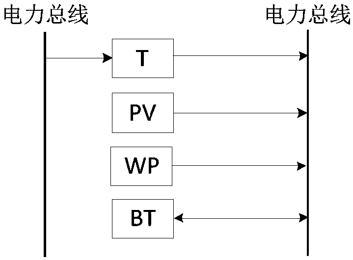
[0044] (1-1) Establish a power-power bus interface model

[0045] Power-Power bus interface model such as figure 1 As shown in the figure, T: transformer, PV: solar energy, WP: wind power, BT: storage battery, the calculation formula is:

[0046] PL out =PL in ·η T +P PV +P WP +P BT (1)

[0047] In formula (1), PL in / PL out Respectively represent the electric energy input / output by the electric power bus, η T Indicates the efficiency of the transformer, P PV Indicates the amount of photovoltaic power generation, P WP Indicates the amount of wind power generation, P BT Indicates the charging / discharging capacity of the battery, positive when discharging and negative when charging.

[0048] The power-power bus interface model integrates transformers, photovol


PUM


Abstract

The invention discloses a modeling method of an energy distributor based on a bus-type structure. The traditional energy system planning only faces the single energy system, which artificially cuts off the optimal allocation of resources in each energy system and reduces the overall energy efficiency. The modeling method of the invention comprises the following steps: 1) establishing a plurality of bus-type interface models according to user requirements; 2) combining a plurality of bus-type interface models according to the actual application scenario to obtain an energy distributor. The invention uniformly dispatches the four energy sources of electricity, heat, cold and gas, reasonably allocates the use paths of the energy sources, and fully exerts the complementary characteristics andsynergistic effects of different energy sources; the invention makes the internal structure of the energy distributor clear and concise, and is convenient for the user to carry out modular modeling, and bus-type modeling is carried out on the interior of the energy distributor according to the type of the energy conversion device.

Description


Claims


Application Information

Patent Timeline
Owner ELECTRIC POWER RES INST OF STATE GRID ZHEJIANG ELECTRIC POWER COMAPNY
Why Eureka
Try Eureka