Static monitoring method for atmospheric electric field

An atmospheric electric field and static monitoring technology, applied in electrostatic field measurement and other directions, can solve the problems of high cost, difficult to reduce volume, complex structure, etc., and achieve the effect of low cost

Inactive Publication Date: 2019-02-15
云南频谱通信网络有限公司
View PDF7 Cites 0 Cited by
  • Summary
  • Abstract
  • Description
  • Claims
  • Application Information

AI Technical Summary

Benefits of technology

This inventive device uses special materials for its purpose during impacts from strong electrical discharges like lighting or static charges on electronic devices. When this happens, there are two ways: one way they detect if these conditions exist without triggering any harmful signals while another method involves creating a protective path through which current flows away from sensitive parts. By measuring their distances close enough together at least 100 m beyond where induced voltages may damage them, we aimed towards developing technology that could help prevent accidents caused by such events happening around us.

Problems solved by technology

This patented technology uses two types of plates: one made up from aluminum or other metals that are fixed together at certain points along their edges for better stability during use. These plates move around when exposed to electrical fields. By measuring this induced voltages across these plates, it becomes possible to determine how strong they were before being struck down due to high levels of solar winds. However, there may still exist some technical problem where existing methods require expensive equipment such as computers.

Method used


Image

  • Static monitoring method for atmospheric electric field
  • Static monitoring method for atmospheric electric field

Examples


Embodiment Construction

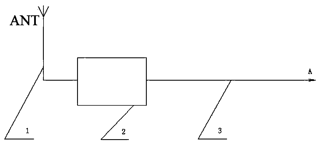
[0016] A method for static monitoring of atmospheric electric field, comprising the following steps:

[0017] Step 1: The atmospheric electric field static monitoring antenna ANT monitors the atmospheric electric field around the equipment in real time. When the surrounding atmospheric electric field voltage increases, no matter whether it is a positive or negative electric field, a weak voltage signal will be induced on the atmospheric electric field monitoring antenna. ;

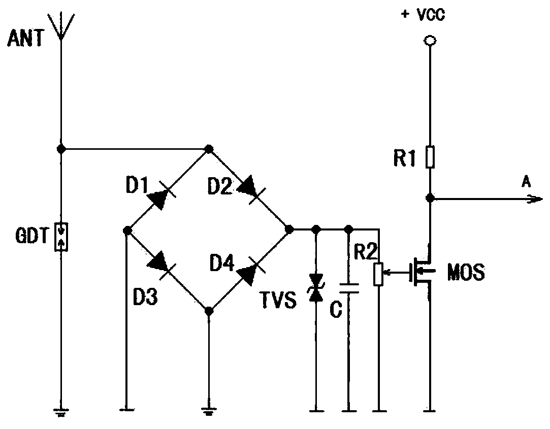
[0018] Step 2: The sensed voltage signal is rectified by a bridge composed of diode D1, diode D2, diode D3 and diode D4;

[0019] Step 3: The rectified signal is sent to an amplification circuit composed of a field effect transistor MOS and a resistor R1 for amplification by adjusting the potentiometer R2, and the amplified signal A is sent to a subsequent circuit for processing.

[0020] In the present invention, a capacitor C for anti-interference is connected between the input terminal of the field effect


PUM


Abstract

The invention relates to a static monitoring method for an atmospheric electric field. The static monitoring antenna for the atmospheric electric field monitors the atmospheric electric field around the device in real time. Either a positive or negative electric field will sense a weak voltage signal on the monitoring antenna for the atmospheric electric field when the atmospheric electric field voltage around the device rises. The sensed voltage signal is rectified by a bridge composed of a diode D1, a diode D2, a diode D3, and a diode D4. The rectified signal is sent to an amplifying circuitcomposed of a field effect transistor and a resistor R1 through an adjustment potentiometer, and the amplified signal is sent to a subsequent circuit for processing. The atmospheric electric field monitoring antenna of the invention has a self-protection function when struck by lightning, and forms an active lightning protection circuit with the subsequent circuit. The positive lightning and thenegative lightning generated by the atmosphere around the protected device can be detected.

Description


Claims


Application Information

Patent Timeline
Owner 云南频谱通信网络有限公司
Why Eureka
Try Eureka