Pipe fitting clamping device

A clamping device and pipe clamp technology, applied in workpiece clamping devices, shearing devices, accessories of shearing machines, etc., can solve the problems of difficult control of clamping force, taking a lot of time, and inability to realize automatic clamping.

Inactive Publication Date: 2019-03-19
刘剑
View PDF5 Cites 10 Cited by
  • Summary
  • Abstract
  • Description
  • Claims
  • Application Information

AI Technical Summary

Benefits of technology

This patented technology allows for automatic adjustment of the grip between two parts (a male element and an expanded member) made up from different materials like metal plugs or pipelines without having any manual interventions during installation process. It achieves this by connecting the tensional motors' driving axis to the expansion members mounted on their mounts via threads. These elements have teeth called wedges which fit into matching holes inside them. A sensory device attached to these components detects changes in pressure caused by movement within the pipeline system. By turning off certain valves at specific points, the actuator activate the power supply to cause the tunneling motion of the thrust balls causing further advancement towards the desired position.

Problems solved by technology

This technical problem addressed by this patented method for connecting thread-connected ferrules without manual labor has been solved through various methods such as clinch guns that can apply high pressure but are expensive compared to automatic tools used at industrial sites due to their complexity and difficulty controllably.

Method used


Image

  • Pipe fitting clamping device
  • Pipe fitting clamping device
  • Pipe fitting clamping device

Examples


Embodiment Construction

[0016] The present invention will be further described below in conjunction with the accompanying drawings and given embodiments.

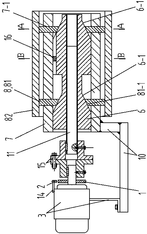
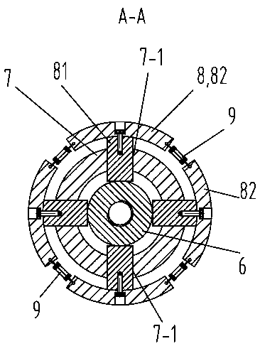
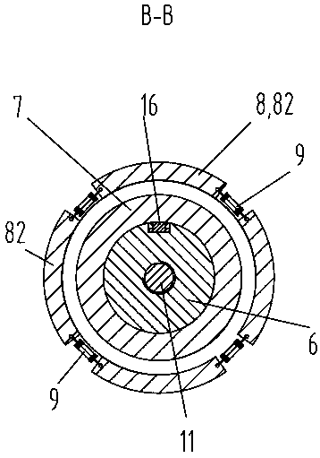
[0017] Such as Figure 1 to Figure 4 As shown, a clamping device for pipe fittings includes a magnetic ring 1, a sensor 2, a tensioning motor 3, a main controller 4, a motor driver 5, a mandrel 6, an expansion block mounting seat 7, an expansion block mechanism 8, a pull Spring 9, frame 10, screw mandrel 11, first switch 12 and second switch 13; Among the present embodiment, magnetic ring 1 selects the two pairs of pole magnetic rings produced by Jiangsu Xinxu Magnetic Technology Co., Ltd. The sensor 2 selects the Hall sensor of model MT4401. The tensioning motor 3 is a servo motor whose model is TLSM04-M00330. The main controller 4 is a PLC programmable controller, and the Mitsubishi FX2NC-PLC programmable controller is selected, and the motor driver 5 is a DC motor drive board whose model is LMD 18200T. Both the first switch 12 and the second sw


PUM


Abstract

The invention discloses a pipe fitting clamping device. The pipe fitting clamping device comprises a magnetic ring, a sensor, a tensioning motor, a main controller, a motor driver, a core shaft, an expansion block mounting seat, an expansion block mechanism, a tension spring, a rack, a lead screw, a first switch and a second switch; a body of the tensioning motor and the expansion block mounting seat are fixedly connected to the rack, and an output shaft of the tensioning motor is in transmission connection with the lead screw; the core shaft is slidably connected to the expansion block mounting seat, and the lead screw and the core shaft are in threaded connection; the expansion block mechanism comprises a plurality of radial sliding blocks and a plurality of expansion blocks, the radialsliding blocks are slidably connected into sliding grooves of the expansion block mounting seat, and the conical faces of the radial sliding blocks are matched with a cone part of the core shaft; themagnetic ring is fixedly connected to the output shaft of the tensioning motor; the sensor is fixedly connected to the body of the tensioning motor; the sensor, the motor driver, the first switch andthe second switch are all electrically connected with the main controller; and the tensioning motor is electrically connected with the motor driver. The pipe fitting clamping device can automaticallyclamp a steel pipe, and clamping force can be automatically controlled.

Description


Claims


Application Information

Patent Timeline
Owner 刘剑
Why Eureka
Try Eureka