Tubing anchor

A kind of oil pipe anchor and sliding pipe technology, which is applied in wellbore/well parts, earthwork drilling and other directions, can solve the problem of excessive wear of sucker rod and oil pipe, large mechanical loss of oil production lifting device, and high tensile strength requirements of oil pipe, etc. problem to avoid bending

Active Publication Date: 2019-03-22
DAQING SHENGWEI MACHINERY MFG
View PDF8 Cites 4 Cited by
  • Summary
  • Abstract
  • Description
  • Claims
  • Application Information

AI Technical Summary

Problems solved by technology

At present, after most tubing anchors are anchored, the tubing string not only cannot rotate, but also cannot move up and down. However, in the thermal recovery of heavy oil, this kind of tubing anchor will cause some problems: during thermal recovery, the tubing string is stretched by heat. long, but the tubing anchor cannot move, which directly causes the tubing string to bend under pressure, which in turn leads to large mechanical losses of the oil production lifting device, low efficiency of

Method used


Image

  • Tubing anchor
  • Tubing anchor
  • Tubing anchor

Examples


Embodiment Construction

[0023] The present invention will be further described below in conjunction with accompanying drawing:

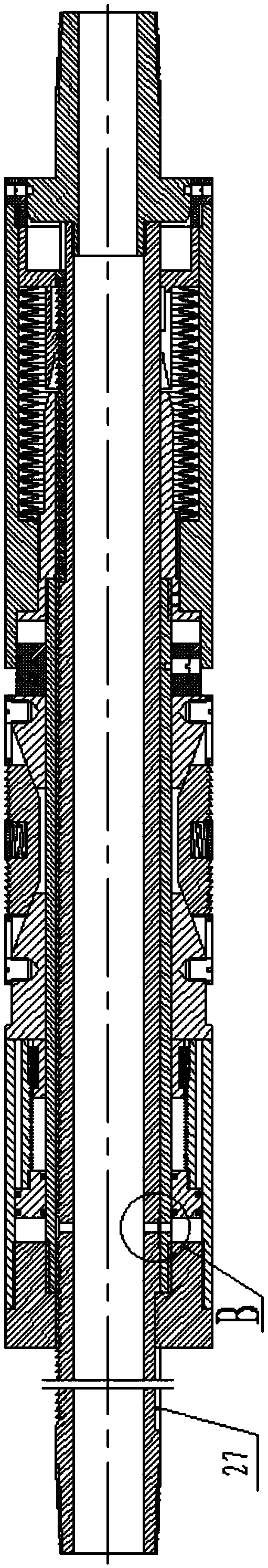
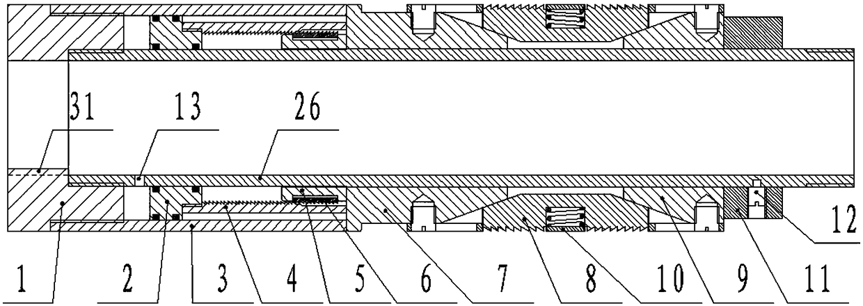
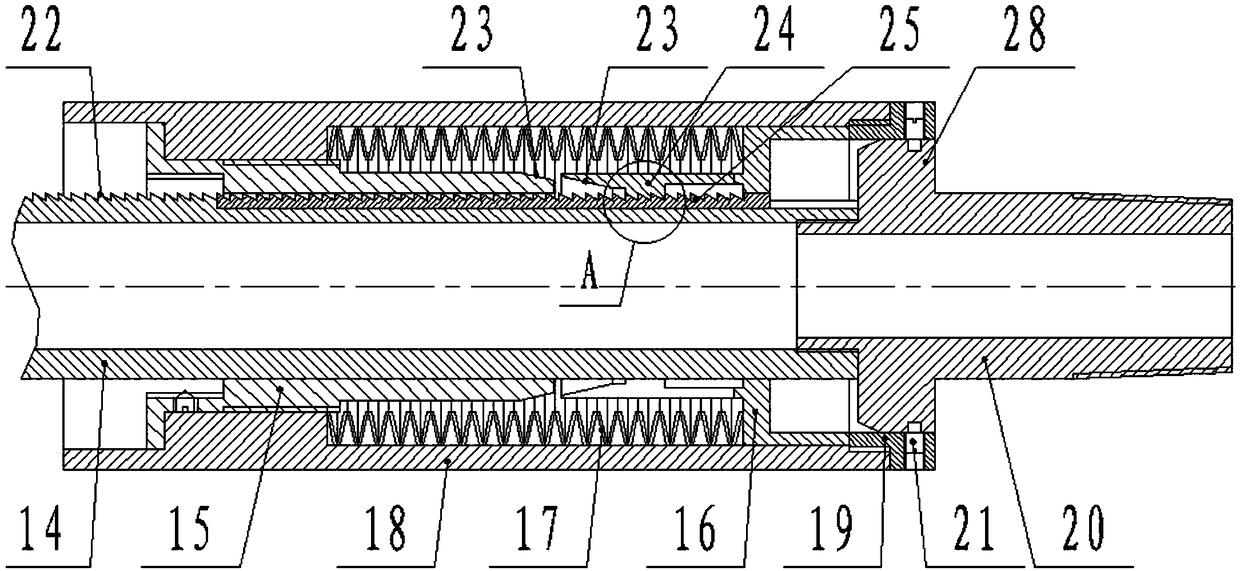
[0024] The invention includes a tubing anchor main body and a pressure-limiting tripping mechanism. The tubing anchor main body is used to realize the basic function of the tubing anchor. The pressure-limiting tripping mechanism enables relative movement between the tubing string and the tubing anchor body, thereby preventing the tubing from creeping. Purpose.

[0025] Tubing anchor main body, its structure includes upper joint 1, central tube 26, piston sleeve 3, setting piston 2, setting sleeve 4, circlip hanger 5, circlip 6, upper cone 7, slips 8, lower cone 9 , the slip installation sleeve 10 and the unsealing ring 11, the upper joint 1 is connected to the upper end of the center pipe 26 by threads, the upper end of the piston sleeve 3 is connected to the outer side of the lower end of the upper joint 1 by threads, the setting piston 2, the setting sleeve 4, the locking B


PUM


Abstract

The invention belongs to the field of oil field oil extraction equipment and particularly relates to a tubing anchor. The tubing anchor comprises a tubing anchor body and also comprises a pressure-limiting tripping mechanism, wherein the pressure-limiting tripping mechanism structurally comprises a sliding pipe, a conical sleeve, a one-way stop sleeve, a disc spring, an outer cylinder, a plug anda lower joint, the outer side of the sliding pipe is provided with a sliding way and a rack, the rack is provided with one-way stop teeth, the disc spring and the one-way stop sleeve are arranged in an annular space between the sliding pipe and the outer cylinder, the upper end and the lower end of the disc spring respectively abut against the outer cylinder and the one-way stop sleeve, the one-way stop sleeve is kept moving away from the conical sleeve under the effect of the disc spring, and the upper end of the one-way stop sleeve is provided with a spring claw. When thermal recovery is stopped, a tubing column is shortened, an axial pull force borne by a tubing and the tubing anchor body is limited in a certain range, so that the pull force produced after tubing column condensation does not affect the set-packing stability of the tubing anchor body and also does not cause challenge of the tensile strength of oil pipes.

Description


Claims


Application Information

Patent Timeline
Owner DAQING SHENGWEI MACHINERY MFG
Why Eureka
Try Eureka