Pneumatic small U-shaped pipe bender

A pipe bender and pneumatic technology, applied in the field of pneumatic small U pipe benders, can solve the problems of large force, large space and large loss.

Pending Publication Date: 2020-02-28
OMS MASCH CO LTD
View PDF1 Cites 0 Cited by
  • Summary
  • Abstract
  • Description
  • Claims
  • Application Information

AI Technical Summary

Benefits of technology

This patented device allows for easier insertion/removing of cores from rails without having to move them back again once they have been inserted. It achieves these benefits due to its design that improves efficiency while reducing costs compared to existing systems.

Problems solved by technology

This patented technical problem addressed in this patents relating to the current multi function composite small upright pipelining tool uses multiple components including a cutter for creation of holes during drilling operations. These tools are expensive due to their complexity and require frequent maintenance because they have many moving parts which can be difficult to manage. Additionally, these tools may generate excessive noise when operated manually without being controlled accurately.

Method used


Image

  • Pneumatic small U-shaped pipe bender
  • Pneumatic small U-shaped pipe bender
  • Pneumatic small U-shaped pipe bender

Examples


Embodiment Construction

[0026] Below, in conjunction with accompanying drawing and specific embodiment, the present invention is described further:

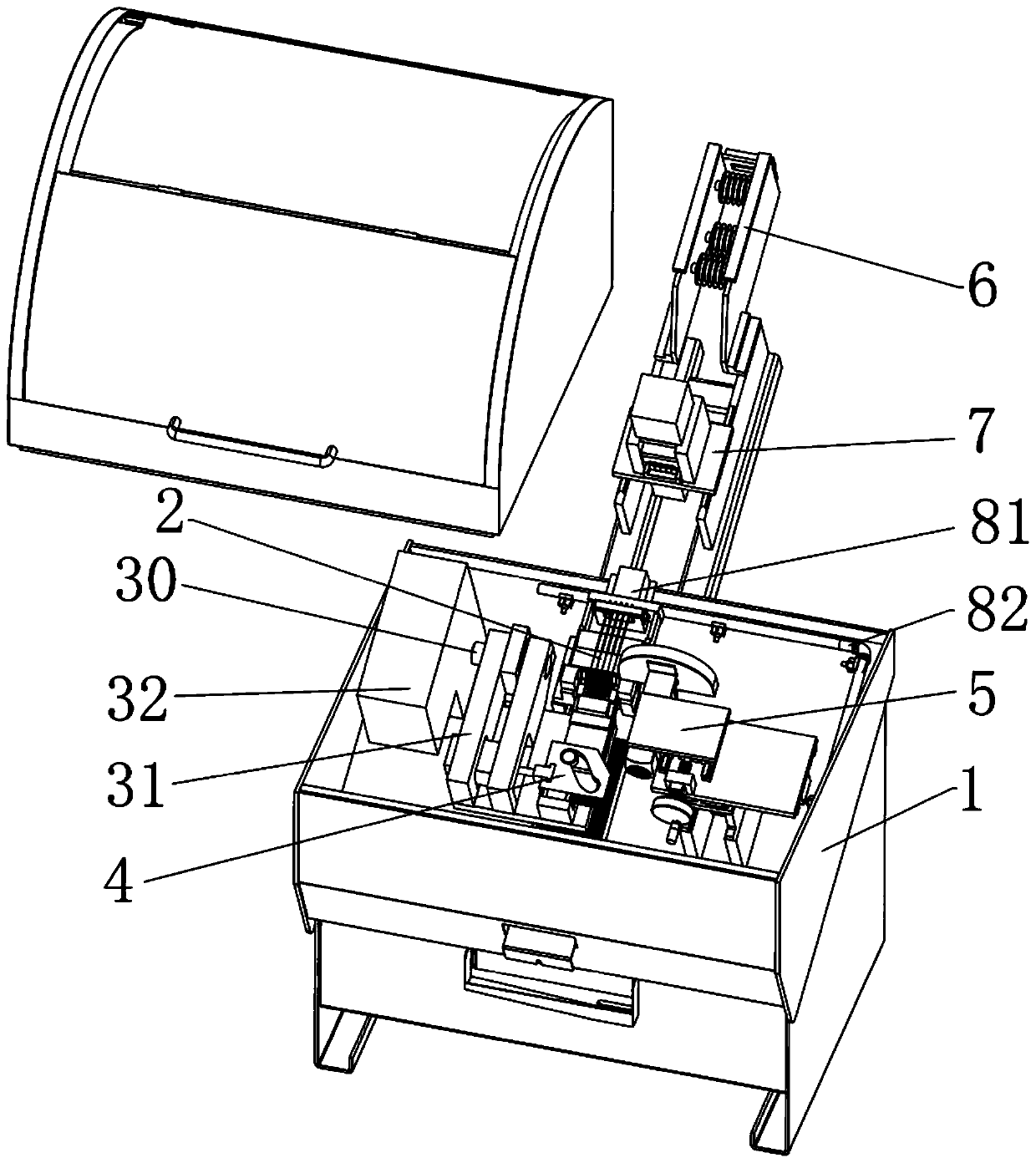
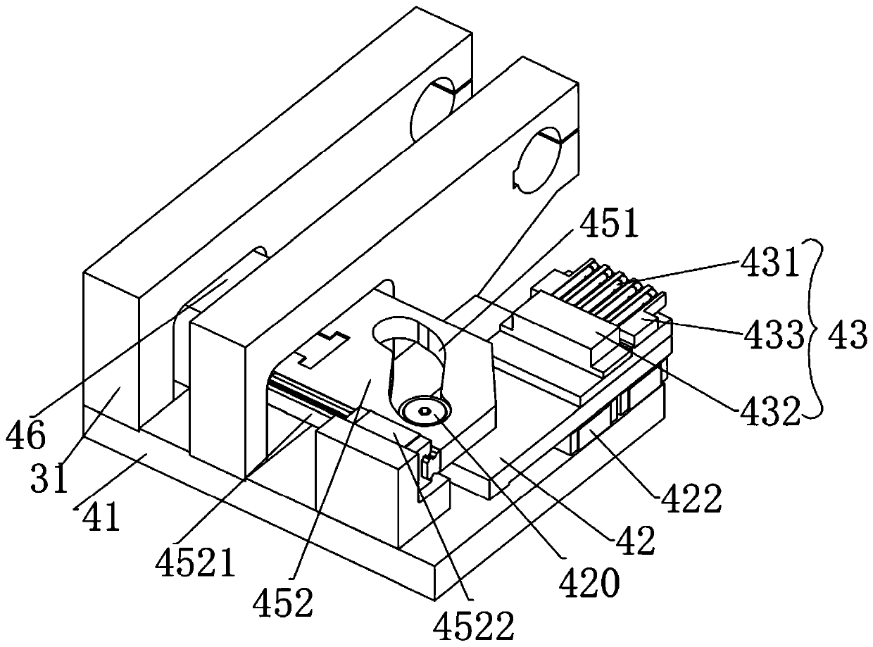
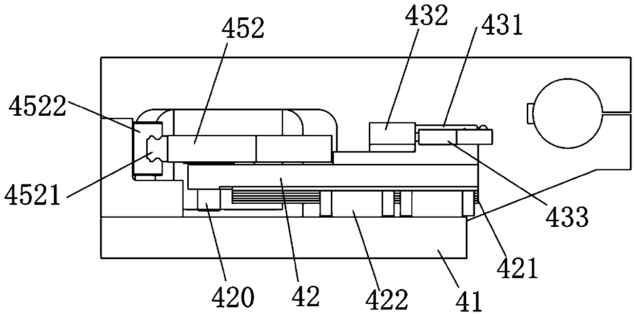
[0027] Such as Figure 1 to Figure 13 as shown, Figure 1 to Figure 13Disclosed is an embodiment of a pneumatic small U pipe bender, a pneumatic small U pipe bender, including a frame 1, on which a bending and clamping mechanism 2, a swing arm 31, a swing arm power mechanism 32 and cutting mechanism 5, the bending and clamping mechanism 2 is used to clamp the workpiece to be bent, the swing arm 31 is hinged with the frame 1 through the swing shaft 30, and the swing arm 31 is driven by the swing arm power mechanism 32 Take the pendulum shaft 30 as the axis to swing toward or away from the bending and clamping mechanism 2, and the cutting mechanism 5 is arranged on one side of the bending and clamping mechanism 2. In the present invention, a core-feeding mechanism 4 is also included. , the core entry mechanism 4 is fixed below the swing arm 31, and is matc


PUM


Abstract

The invention discloses a pneumatic small U-shaped pipe bender. The pneumatic small U-shaped pipe bender comprises a frame, wherein a bending clamping mechanism, a swing arm, a swing arm power mechanism, a cutting mechanism and a core feeding mechanism are arranged on the frame, wherein the swing arm is hinged to the frame through a swing shaft and is driven by the swing arm power mechanism to swing in a direction close to or far away from the bending clamping mechanism by taking the swing shaft as an axis; the core feeding mechanism is fixed below the swing arm and matched with the bending clamping mechanism to jointly clamp a workpiece to be bent; and the core feeding mechanism comprises an installation base plate, a core feeding sliding plate is arranged on the installation base plate and can move back and forth along an X axis on the installation base plate, a core shaft assembly is arranged at one end of the core feeding sliding plate, a cam and a track groove are arranged at theother end of the core feeding sliding plate, the cam is connected with the core feeding sliding plate through a roller, one end of the roller is fixed to the core feeding sliding plate, and the otherend of the roller penetrates into the track groove. Therefore, the pneumatic small U-shaped pipe bender has the advantages of reinforcement effect, larger core pulling force, lower cost and environmental protection.

Description


Claims


Application Information

Patent Timeline
Owner OMS MASCH CO LTD
Why Eureka
Try Eureka