Two-degree-of-freedom parallel mechanism easy to control

A technology of parallel connection and revolving pair, which is applied in the direction of program-controlled manipulators, manipulators, manufacturing tools, etc., which can solve problems such as difficult control and strong coupling, reduce processing costs and solve poor kinematic decoupling

Pending Publication Date: 2019-03-29
HENAN UNIV OF SCI & TECH
View PDF2 Cites 0 Cited by
  • Summary
  • Abstract
  • Description
  • Claims
  • Application Information

AI Technical Summary

Problems solved by technology

[0003] The purpose of the present invention is to design an easy-to-control two-degree-of-freedom parallel mechanism to solve technical problems such as strong coupling and difficult control of the existing two-degree-of-freedom two-rotation parallel mechanism

Method used


Image

  • Two-degree-of-freedom parallel mechanism easy to control

Examples


Example Embodiment

[0014] The technical solution of the present invention will be further described through specific implementations in conjunction with the accompanying drawings.

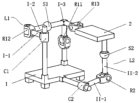
[0015] As shown in the figure, an easy-to-control two-degree-of-freedom parallel mechanism includes a fixed platform, a moving platform, and a first branch kinematic chain and a second branch kinematic chain connecting the two platforms.

[0016] The first branch kinematic chain L1 is a mixed chain, and a single-open chain composed of a first cylinder pair C1, a second rotating pair R12 and a first ball pair S1 forms a closed loop with the first rotating pair R11 and a third rotating pair R13 is connected in series, wherein the first cylinder pair C1 and the first rotating pair R11 are connected to the fixed platform 1, and are arranged diagonally on the fixed platform 1, the third rotating pair R13 is connected to the movable platform 2, and the second rotating pair The two ends of R12 are respectively connected to one end


PUM


Abstract

The invention relates to a two-degree-of-freedom parallel mechanism easy to control. The mechanism consists of a fixed platform, a movable platform and two branch motion chains connected with the fixed platform and the movable platform, wherein the first branch motion chain is formed by connecting a spatial closed loop structure with a third rotating pair in series, the spatial closed loop structure is formed by connecting a unidirectional opening chain with a first rotating pair and used for controlling one degree of rotation freedom of the movable platform, and the unidirectional opening chain is composed of a first cylindrical pair, a second rotating pair and a first spherical pair; the second branch motion chain is a unidirectional chain which is formed by connecting a second cylindrical pair, a fourth rotating pair and a second spherical pair and used for controlling the other one degree of rotation freedom of the movable platform. The unidirectional opening chain in the first branch motion chain of the mechanism is identical with the second branch motion chain in structure, the machining cost is reduced, the speed Jacobian matrix of the mechanism is a diagonal matrix, and theoutput speed and input speed of the movable platform are in a one-to-one corresponding control relationship. Thus, the problems that common parallel mechanisms are poor in kinematic decoupling performance and difficult for control design are solved.

Description


Claims


Application Information

Patent Timeline
Owner HENAN UNIV OF SCI & TECH
Why Eureka
Try Eureka