Single interference source positioning method based on virtual boundary point fitting

A virtual boundary and positioning method technology, applied in transmission monitoring, electrical components, transmission systems, etc., to achieve the effect of simple steps, easy implementation, and high positioning accuracy

Active Publication Date: 2019-03-29
ANHUI UNIVERSITY OF TRADITIONAL CHINESE MEDICINE
View PDF5 Cites 0 Cited by
  • Summary
  • Abstract
  • Description
  • Claims
  • Application Information

AI Technical Summary

Problems solved by technology

[0007] The technical problem to be solved by the present invention is to provide a single interference source positioning method based on virtual boundary point fitting, which can solve the problem of accurately detecting the location of the interference source when the sensor network is attacked by a single interference source

Method used


Image

  • Single interference source positioning method based on virtual boundary point fitting
  • Single interference source positioning method based on virtual boundary point fitting
  • Single interference source positioning method based on virtual boundary point fitting

Examples


Example Embodiment

[0042] The preferred embodiments of the present invention will be described in detail below with reference to the accompanying drawings, so that the advantages and features of the present invention can be more easily understood by those skilled in the art, so as to make a clearer and clearer definition of the protection scope of the present invention.

[0043] See figure 1 , The embodiment of the present invention includes:

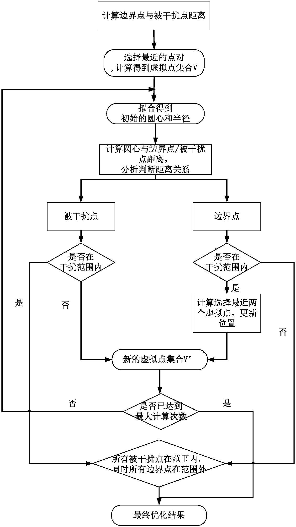
[0044] A single interference source positioning method based on virtual boundary point fitting includes the following steps:

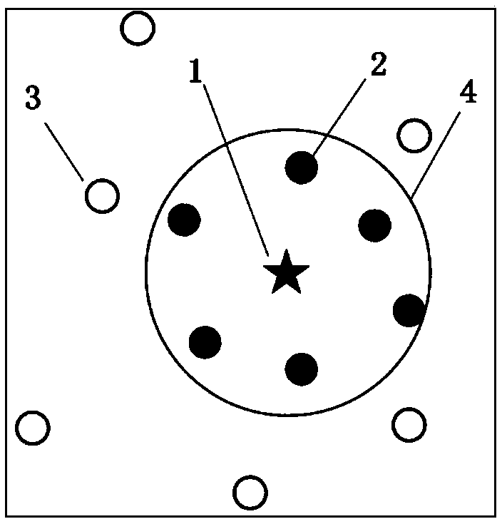
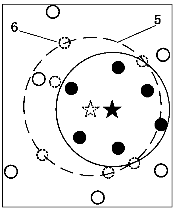
[0045] S1: Calculate the distance between the boundary node 3 and the disturbed node 2 in the sensor network, select the nearest point pair, and obtain the coordinate value of the virtual boundary node 6; combine figure 2 , The center of the actual interference boundary 4 is the interference source node 1. The specific calculation process includes:

[0046] S1.1: Calculate the distance between each point in the boundary node set B and each


PUM


Abstract

The invention discloses a single interference source positioning method based on virtual boundary point fitting. The method comprises the following steps: S1: calculating the distance between a boundary node and an interfered node in a sensor network, selecting the nearest point pair, and obtaining a coordinate value of a virtual boundary point; S2: fitting a circular area of an interference rangeby using the virtual boundary node to obtain primary interference source coordinates and a primary interference distance; S3: analyzing and calculating a positional relationship among the interference range, the boundary node and the interfered node, and adjusting the calculation to obtain a new virtual boundary node; S4: performing re-fitting calculation by using the new virtual boundary node toobtain new interference source coordinates and a new interference distance; and S5: repeating the steps S2 to S4, and preforming multiple iterations until the optimal interference source coordinatesand the optimal interference distance are calculated. The method disclosed by the invention is simple in steps, easy to implement and high in positioning accuracy, and the problem that the location ofthe interference source needs to be accurately detected when the sensor network is attacked by a single interference source is solved.

Description


Claims


Application Information

Patent Timeline
Owner ANHUI UNIVERSITY OF TRADITIONAL CHINESE MEDICINE
Why Eureka
Try Eureka