System and method for parallel test of flowmeter
A parallel test, flowmeter technology, applied in liquid/fluid solid measurement, measurement device, test/calibration device, etc., can solve problems such as low test efficiency and achieve the effect of improving test efficiency
- Summary
- Abstract
- Description
- Claims
- Application Information
AI Technical Summary
Benefits of technology
Problems solved by technology
Method used
Image


Examples
Embodiment 1
[0051] A system for performing parallel tests on flowmeters, comprising: a calibrator, a flowmeter, an industrial computer and a multi-serial port communication card;
[0052] There are a plurality of flowmeters; the gas inlet of the calibrator is communicated with the zero gas source, and the gas outlet of the calibrator is communicated with the gas inlets of each of the flowmeters; each of the flowmeters is connected with the calibration There is a solenoid valve on the connecting pipe of the instrument;
[0053]The communication interface of the industrial computer is connected to the bus interface of the multi-serial communication card, and the multiple ports of the multi-serial communication card are respectively electrically connected to the calibrator, the digital quantity collector and a plurality of the flowmeters; Multiple output interfaces of the digital quantity collector are respectively electrically connected to multiple solenoid valves;
[0054] The calibrator is
Embodiment 2
[0056] This example is a method for parallel testing using the system of Example 1.
[0057] figure 1 It is a flow chart of the method for performing parallel tests on flowmeters according to Embodiment 2 of the present invention.
[0058] see figure 1 , the method includes:
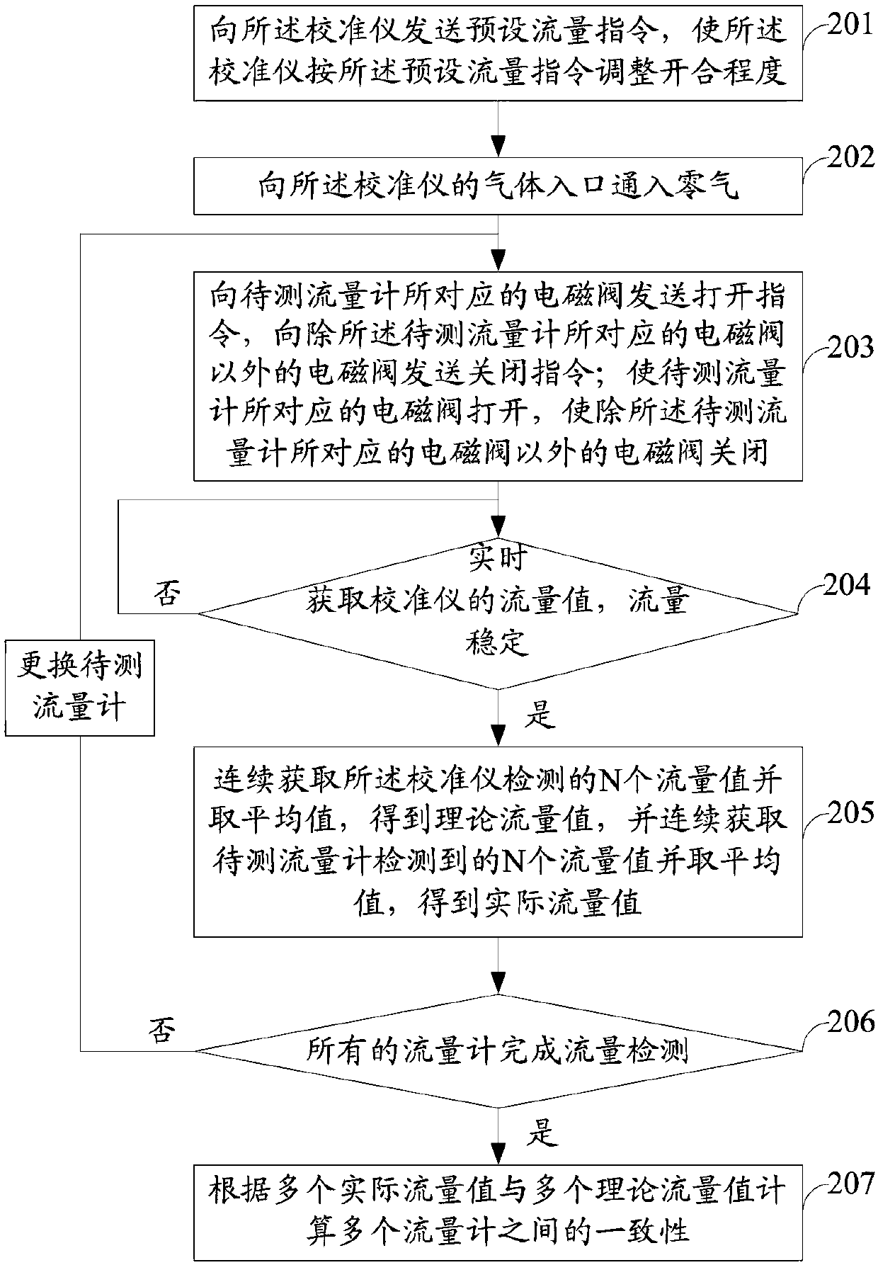
[0059] Step 201: Send a preset flow command to the calibrator, so that the calibrator adjusts the opening and closing degree according to the preset flow command;
[0060] Step 202: injecting zero gas into the gas inlet of the calibrator;
[0061] Step 203: Send an open command to the solenoid valve corresponding to the flowmeter to be tested, and send a close command to the solenoid valves other than the solenoid valve corresponding to the flowmeter to be tested, so that the solenoid valve corresponding to the flowmeter to be tested is opened, Closing solenoid valves other than the solenoid valve corresponding to the flowmeter to be measured;
[0062] Step 204: Obtain the flow value of the calibrator
Embodiment 3
[0082] This embodiment 3 is a more specific embodiment relative to the embodiment 1.
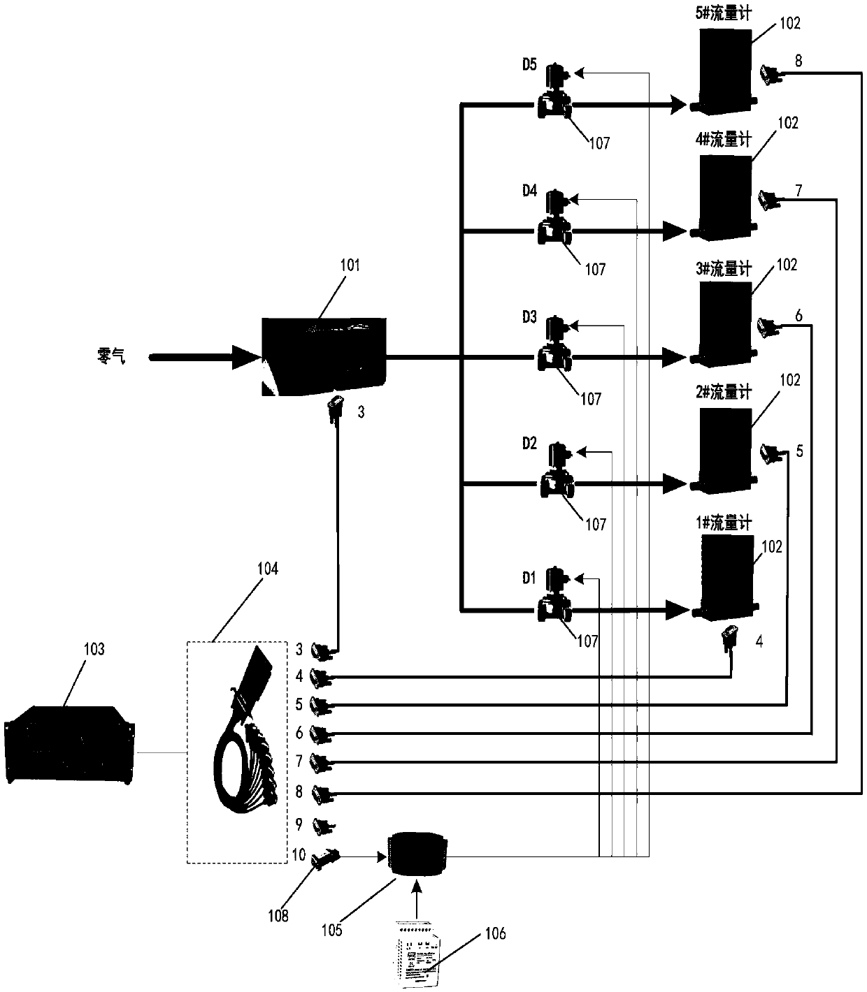
[0083] figure 2 It is a system structure diagram of a system for performing parallel tests on flowmeters in Example 3 of the present invention.
[0084] see figure 2 , the system for carrying out parallel tests on flowmeters in this embodiment 3, comprising: a calibrator 101, a flowmeter 102, an industrial computer 103, a multi-serial communication card 104, a digital quantity collector 105 and a switching power supply 106;
[0085] There are 5 flowmeters 102, numbered respectively 1#, 2#, 3#, 4#, 5#; the gas inlet of the calibrator is connected to the zero gas source, and the gas outlet of the calibrator is connected to each The gas inlets of the flowmeters 102 are connected; a solenoid valve 107 is arranged on the communication pipe between each of the flowmeters and the calibrator, and the numbers of the solenoid valves 107 corresponding to the five flowmeters 102 are D1 and D2. , D3, D
PUM
 Abstract
Description
Claims
Application Information
 - R&D Engineer
- R&D Manager
- IP Professional
- Industry Leading Data Capabilities
- Powerful AI technology
- Patent DNA Extraction
Browse by: Latest US Patents, China's latest patents, Technical Efficacy Thesaurus, Application Domain, Technology Topic.
© 2024 PatSnap. All rights reserved.Legal|Privacy policy|Modern Slavery Act Transparency Statement|Sitemap