Inductive sensor simulation test method

An analog test, inductive technology, applied in the field of sensor testing, can solve the problems of inconvenient testing, inability to achieve miniaturization, and high development cost of test equipment, reducing complexity and weight, improving integration, and good economy.

Pending Publication Date: 2019-05-03
SUZHOU CHANGFENG AVIATION ELECTRONICS
View PDF1 Cites 2 Cited by
  • Summary
  • Abstract
  • Description
  • Claims
  • Application Information

AI Technical Summary

Problems solved by technology

The current traditional testing methods have the following disadvantages: most of them are based on static testing, which cannot easily simulate the actual product ap

Method used


Image

  • Inductive sensor simulation test method
  • Inductive sensor simulation test method

Examples


Embodiment Construction

[0020] The following is attached figure 1 The preferred embodiments of the present invention are described, and it should be understood that the preferred embodiments described here are only used to illustrate and explain the present invention, and are not intended to limit the present invention.

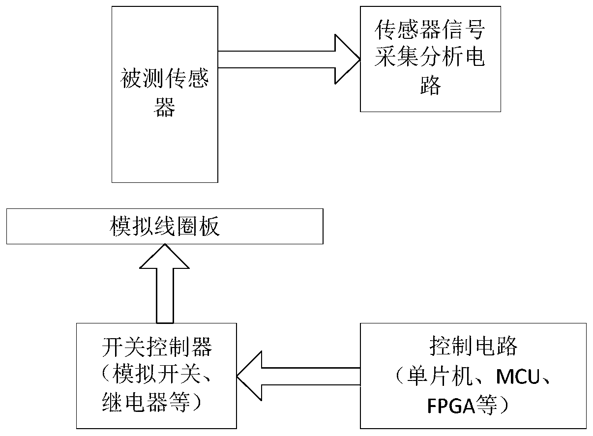
[0021] An inductive sensor simulation test method, comprising the following:

[0022] (1) Design the simulation coil board according to the test requirements, and connect the two ends of the simulation coil on the simulation coil board to the switch controller;

[0023] (2) Design the control circuit to realize the conduction of the analog coil by controlling the switch of the switch controller;

[0024] (3) By controlling the conduction of the analog coil, the analog coil forms a closed coil, and then forms a closed conductor surface on the test end surface of the inductive sensor to simulate the measured object passing through the test end of the inductive sensor;

[0025] (4) Chan


PUM


Abstract

The invention discloses an inductive sensor simulation test method. The method comprises steps that a simulation coil plate is designed according to test requirements, two ends of a simulation coil ofthe simulation coil plate are connected with a switch controller to design a control circuit, and conduction of the simulation coil is realized through controlling a switch of the switch controller;through controlling conduction of the simulation coil, the simulation coil is made to form a closed coil, a closed conductor surface is formed on an inductive sensor test end surface to simulate a measured object through an inductive sensor test end; induction of the inductive sensor test end is changed, and the corresponding test physical quantity is outputted by an inductive sensor; the obtainedtest physical quantity is compared with a control signal of the control circuit, and measurement accuracy of the inductive sensor is calculated and obtained. The method is advantaged in that the simulation test of multiple types of inductive sensors can be excellently realized, on the basis of the routine static test, the sensor simulation test of the measured object under the high speed movementcondition can be further realized.

Description


Claims


Application Information

Patent Timeline
Owner SUZHOU CHANGFENG AVIATION ELECTRONICS
Why Eureka
Try Eureka